A highly compact closed-cycle radial turbine power generation system rotor

A technology of compact closed power generation system, which is applied in hydroelectric power generation, engine components, non-variable pumps, etc., can solve the problems affecting the reliability of the closed cycle turbine power generation system, the rotor connection strength cannot be effectively guaranteed, the connection Part interference reduction and other issues, to achieve high compactness, enhance stability, improve the overall rigidity

Active Publication Date: 2022-07-12
BEIJING POWER MACHINERY INST
View PDF4 Cites 0 Cited by
  • Summary
  • Abstract
  • Description
  • Claims
  • Application Information

AI Technical Summary

Problems solved by technology

The existing rotor structure adopts interference connection. Although the coaxiality between the parts of the rotor can be guaranteed to a certain extent, the strength of the interference connection of the rotor depends on the assembly size and tolerance of the parts. The processing accuracy of the parts puts forward very high requirements; in addition, the rotor is affected by centrifugal load, thermal load and aerodynamic load during the working process, the actual interference of the connecting parts will be reduced during work, and the connection strength of the rotor cannot be effectively guaranteed , the parts are easy to loosen, seriously affecting the working reliability of the closed cycle turbine power generation system
In addition, the repeatability of this rotor structure is poor

Method used


Image

  • A highly compact closed-cycle radial turbine power generation system rotor
  • A highly compact closed-cycle radial turbine power generation system rotor
  • A highly compact closed-cycle radial turbine power generation system rotor

Examples


Embodiment Construction

[0025] It should be noted that the embodiments of the present invention and the features of the embodiments may be combined with each other under the condition of no conflict.

[0026] The present invention will be described in detail below with reference to the accompanying drawings and in conjunction with the embodiments.

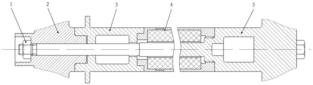
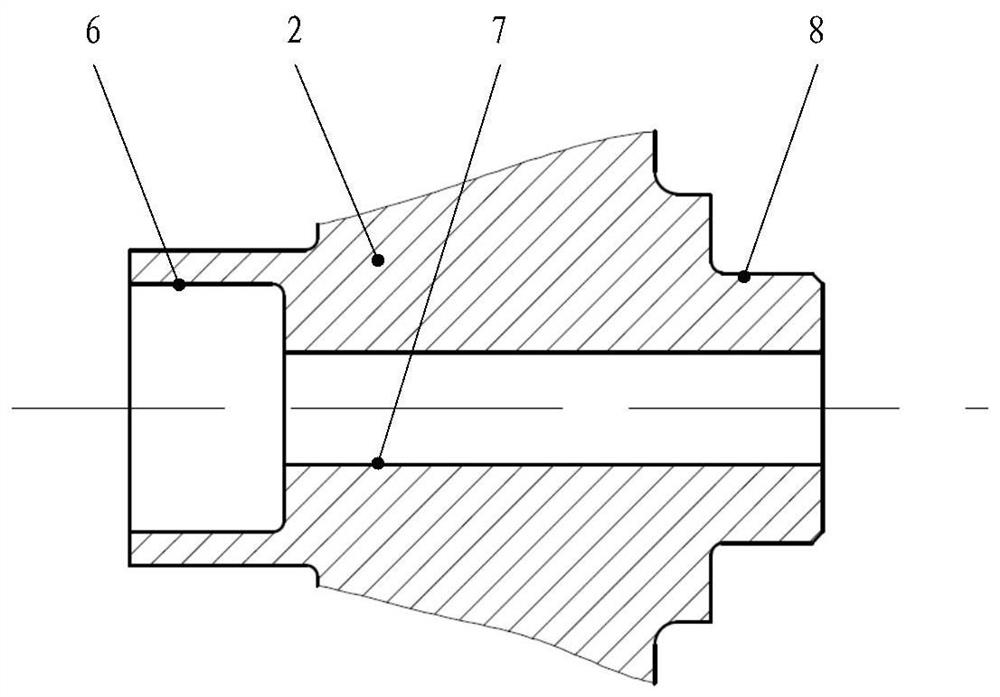
[0027]A rotor structure of a highly compact closed-cycle radial turbine power generation system includes a lock nut 1 , a compressor impeller 2 , a shaft sleeve 3 , a motor shaft 4 and a turbine shaft 5 . The locking nut 1 is assembled on the turbine shaft close to one end of the compressor, and the thread rotation direction of the locking nut 1 is opposite to the rotation direction of the rotor of the turbine power generation system during operation; the compressor impeller 2 is close to the locking nut. One end has an annular protective sleeve 6, the compressor impeller 2 has a central through hole 7, the compressor impeller 2 has an outer cylindrical s...


PUM


Abstract

The invention relates to a rotor of a high-compact closed-cycle radial turbine power generation system, comprising a lock nut, a compressor impeller, a shaft sleeve, a motor shaft and a turbine shaft. The shaft sleeve is provided with a thrust annular end face, the two ends of the shaft sleeve are respectively provided with inner cylindrical surfaces assembled with the compressor impeller and the motor shaft, and the shaft sleeve is provided with through holes and threaded holes assembled with the turbine rotating shaft. On the basis of rationally designing the size parameters of the rotor components and completing the processing and manufacturing, firstly assemble the motor shaft, secondly assemble the motor shaft and the turbine shaft, then assemble the shaft sleeve, the motor shaft and the turbine shaft, and finally assemble the compressor. The assembly between the impeller, bushing, turbine shaft and lock nut forms a complete rotor structure. The rotor can reduce the space size of the rotor of the closed-cycle radial flow turbine power generation system, which is conducive to realizing high compactness of the system, and at the same time, can improve the rigidity of the rotor, which is helpful for improving the working reliability of the turbine power generation system.

Description

technical field [0001] The invention belongs to the field of structural design of a closed-cycle radial-flow turbine power generation system, and in particular relates to a rotor of a highly compact closed-cycle radial-flow turbine power generation system. Background technique [0002] As a new and efficient form of thermal power conversion, the closed-cycle turbine power generation system can realize the conversion of thermal energy to electrical energy through thermal processes such as heat absorption, expansion work, heat release, and compression with the help of a certain gaseous working medium in a closed environment. A typical closed-cycle radial flow turbine power generation system is structurally composed of turbines, compressors, motors, regenerators and other components. [0003] The rotor of the closed-cycle radial turbine power generation system includes two parts, the power rotor and the motor rotor, which are composed of a turbine and a compressor. It is one of...

Claims


Application Information

Patent Timeline
Patent Type & Authority Patents(China)
IPC IPC(8): F01D15/10F01D15/08F01D5/04F01D5/02F01D25/00F04D29/26F04D25/04F04D29/60F04D29/05
CPCF01D15/10F01D15/08F01D5/04F01D5/026F01D25/00F04D29/26F04D29/266F04D25/045F04D29/601F04D29/05F05D2230/60Y02E10/20
Inventor 王正马同玲侯泽兵张华
Owner BEIJING POWER MACHINERY INST
Why Eureka
Try Eureka