Circumferential resistance drive clutch

A clutch and resistance technology, applied in the field of clutches, can solve the problems of the output force of the electromagnetic clutch being small and difficult to large, the complex logic control of the ECU electronic control unit, and the maximum torque limit of the electromagnetic clutch, etc. accurate effect

Pending Publication Date: 2019-10-15
邓林萍
View PDF0 Cites 1 Cited by
  • Summary
  • Abstract
  • Description
  • Claims
  • Application Information

AI Technical Summary

Problems solved by technology

[0003] At present, the electromagnetic clutch is usually used to realize the clutch transmission of the driving wheel and the driven wheel, but it has the following disadvantages: 1. The production cost is high; 2. The maximum torque of the electromagnetic clutch is limited by the size and weight requirements, and the torque of the small size electromagnetic clutch is small and difficult to realize. large output power
3. Complex logic control of ECU electronic control unit
[0004] However, the traditional mechanical overrunning clutch cannot be used because the door is under the action of gravity when going up and downhill.

Method used


Image

  • Circumferential resistance drive clutch
  • Circumferential resistance drive clutch
  • Circumferential resistance drive clutch

Examples


Embodiment Construction

[0055] The present invention will be described in further detail below in conjunction with the accompanying drawings. It should be noted that the words "front", "rear", "left", "right", "upper" and "lower" used in the following description refer to the directions in the drawings, and the words "inner" and "outer ” refer to directions towards or away from the geometric center of a particular part, respectively.

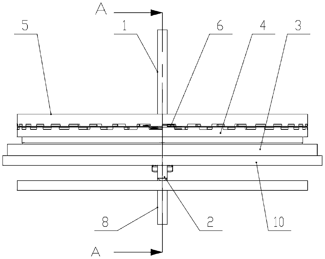
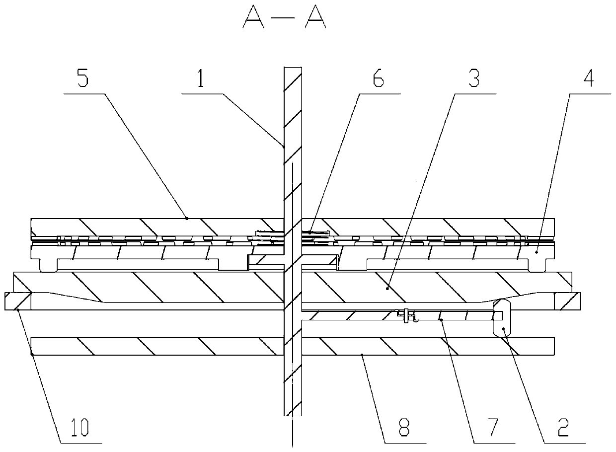
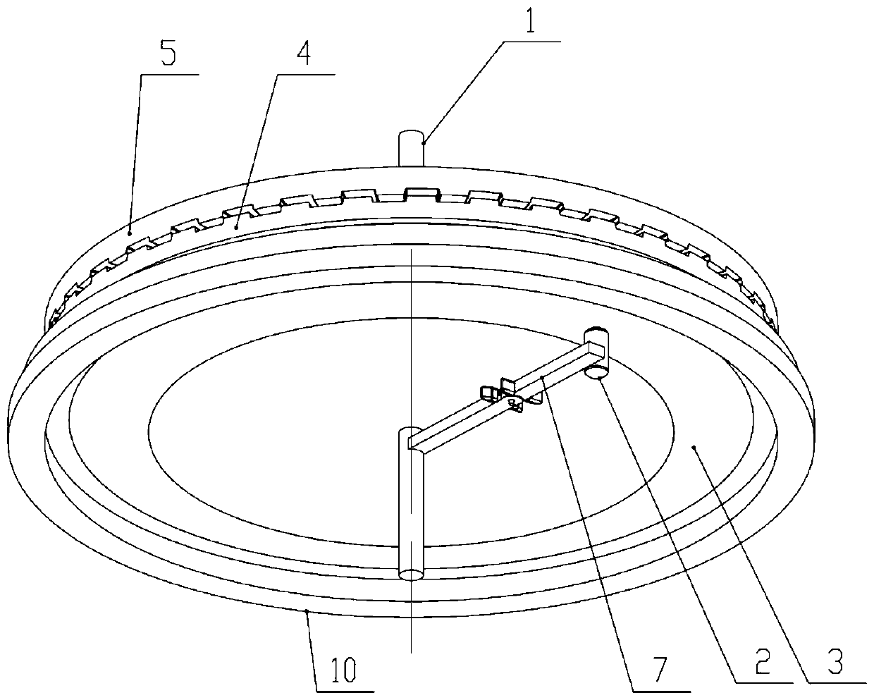
[0056] Figure 1 to Figure 14 A circumferential drag actuated clutch according to an embodiment of the invention is schematically shown. As shown in the figure, the device includes a driving part, several driving blocks 2, a circumferential resistance mechanism, a switching part, a motion conversion mechanism, a return assembly and a driven wheel 5,

[0057] The circumferential resistance mechanism, the drive block 2, the driving part, the switching part and the driven wheel 5 rotate around the center line of the main shaft 1, and the driving part is controlled by th...


PUM


Abstract

The invention discloses a circumferential resistance drive clutch. The circumferential resistance drive clutch includes a driving portion, a driving block, a circumferential resistance mechanism, a switching portion, a motion converting mechanism, a returning member and a driven wheel; the circumferential resistance mechanism, the driving portion, the switching portion and the driven wheel rotatearound a spindle center line, the driving portion is controlled by a power source to rotate or be static, the driving block is connected with the driving portion and is controlled by the driven portion to rotate or be static, meanwhile, the driving block can bear the resistance effect of the circumferential resistance mechanism to generate radial displacement or axial displacement, the motion converting mechanism converts the displacement change of the driving block into up-and-down motion or radial movement of the switching portion, then the switching portion and the driven wheel are integrally combined, the driven wheel is controlled by the power source to rotate, and the returning member enables the driven wheel to separate from the switching portion, and the driven wheel is freely rotated. The circumferential resistance drive clutch has the effects of being simple in structure, low in cost, stable in control and capable of achieving high torque transmission.

Description

technical field [0001] This invention relates to clutches, and more particularly to circumferential drag actuated clutches. Background technique [0002] In order to improve the convenience of use, automobile doors such as sliding doors and sliding doors are gradually equipped with automatic door opening and closing drive modules. Due to various reasons such as safety and usage habits, the door needs to be manually opened and closed at the same time. This requires that the drive module be equipped with a clutch to realize automatic and manual switching. [0003] At present, the electromagnetic clutch is usually used to realize the clutch transmission of the driving wheel and the driven wheel, but it has the following disadvantages: 1. The production cost is high; 2. The maximum torque of the electromagnetic clutch is limited by the size and weight requirements, and the torque of the small size electromagnetic clutch is small and difficult to realize. Great output power. 3...

Claims


Application Information

Patent Timeline
Patent Type & Authority Applications(China)
IPC IPC(8): F16D11/04F16D13/58F16D13/70F16H37/12
CPCF16D11/04F16D13/58F16D13/70F16H37/124
Inventor 李先让
Owner 邓林萍
Why Eureka
Try Eureka