Electromagnet with vacuum adsorption function

A vacuum adsorption, electromagnet technology, applied in the valve operation/release device, valve details, diaphragm valve and other directions, can solve the problems of inconvenient maintenance, untimely opening of the diaphragm, inflexible configuration, etc., to ensure the on-off Reliability, easy operation and maintenance, flexible and convenient configuration

Inactive Publication Date: 2019-10-15
SHANGDONG ZHONGBAOKANG MEDICAL DEVICES
View PDF0 Cites 1 Cited by
  • Summary
  • Abstract
  • Description
  • Claims
  • Application Information

AI Technical Summary

Problems solved by technology

At present, the electromagnets used in the Fresenius blood component separators on the market only have a simple on-off function. When cooperating with the control box, it is easy to cause the diaphragm to not be opened in time, or it is necessary to use an external vacuum sealing system to realize the control of the pipeline. control function
At present, the electromagnets used in blood component collection equipment on the market have complex structures, large product volume, inflexible configuration, inconvenient integration and combination, and are not suitable for later optimized products; due to the complex structure of the product, its stability is relatively low. Poor, prone to problems such as poor sealing, leakage, blockage, etc., resulting in the failure of control disconnection and suction, and it is not easy to maintain

Method used


Image

  • Electromagnet with vacuum adsorption function
  • Electromagnet with vacuum adsorption function
  • Electromagnet with vacuum adsorption function

Examples


Embodiment Construction

[0019] The present invention will be further described below in conjunction with accompanying drawing:

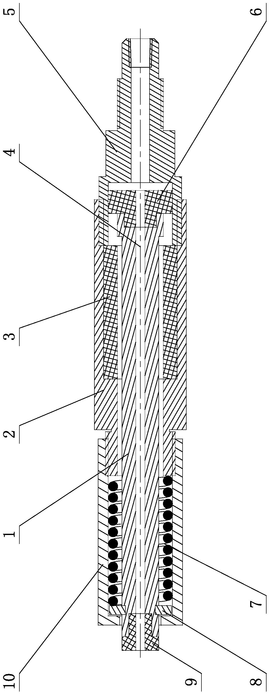
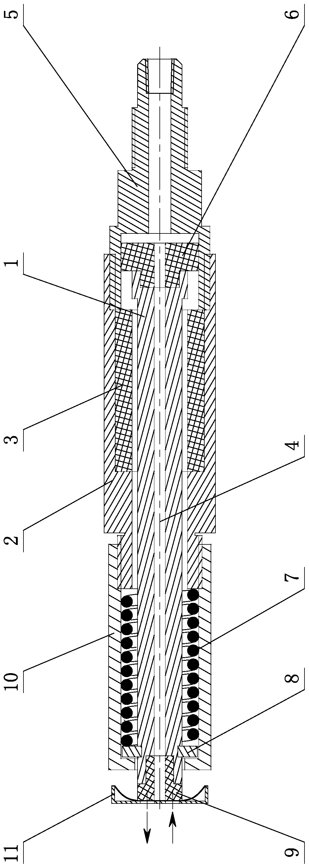
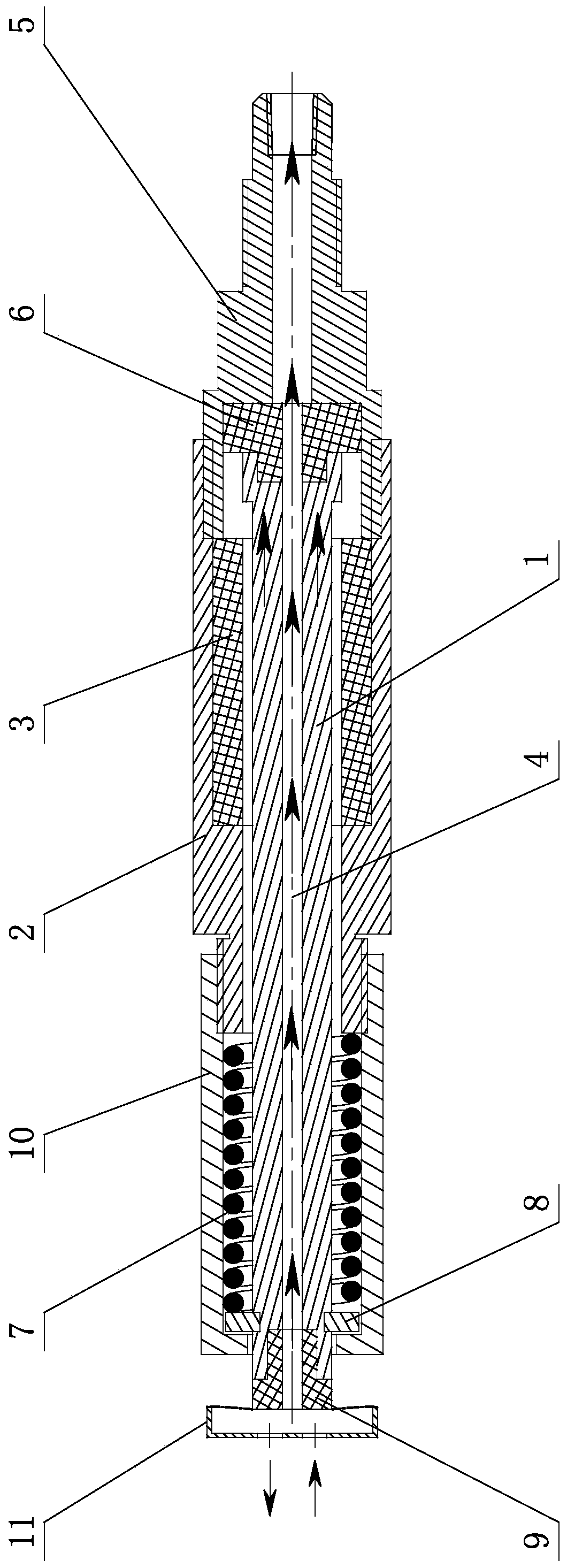
[0020] like Figure 1-Figure 3 , the electromagnet with vacuum adsorption function according to the present invention includes a hollow cylinder 2, the hollow cylinder 2 is connected with a hollow back seat 5 at the tail, the inner holes of the hollow cylinder 2 and the hollow back seat 5 are all stepped, and the pressure rod 1 runs through the inner hole of the hollow cylinder 2, and the outer circumference of the pressure rod 1 in the large hole end of the hollow cylinder 2 is covered with a coil frame, and the coil frame is wound with an electromagnetic coil 3; the head of the pressure rod 1 extends out of the hollow cylinder 2, and the outer circumference of the head of the pressure rod 1 is fixed with an opening retaining ring 8, and the outer circumference of the pressure rod 1 between the opening retaining ring 8 and the head of the hollow cylinder 2 is covered with ...


PUM


Abstract

The invention belongs to the field of devices for blood component acquisition equipment, and relates to an electromagnet with a vacuum adsorption function. The electromagnet comprises a hollow barrelbody. The tail of the hollow barrel body is connected with a hollow rear seat, inner holes of the hollow barrel body and the hollow rear seat are in step shapes, a pressing rod penetrates through theinner hole of the hollow barrel body, the periphery of the portion, in the large hole end of the inner hole of the hollow barrel body, of the pressing rod is sleeved with a coil framework, and an electromagnetic coil is wound outside the coil framework. The head of the pressing rod stretches out of the inner hole of the hollow barrel body, a split washer is fixed to the periphery of the head of the pressing rod, and the periphery of the portion, between the split washer and the head of the hollow barrel body, of the pressing rod is sleeved with a spring. The pressing rod is of a hollow structure, a center through hole of the pressing rod communicates with the inner hole of the hollow rear seat, and the small head end of the inner hole of the hollow rear seat is connected with a vacuumizingdevice. The electromagnet is small in size, flexible and convenient to configure and high in universality, standardization and upgrading and updating of products are easily achieved, and operation and maintenance are facilitated; and the electromagnet independently cooperates with a diaphragm type control box, and the on-off reliability of a pipeline is guaranteed.

Description

technical field [0001] The invention relates to a device with a vacuum adsorption function, which belongs to the field of devices for collecting blood components. Background technique [0002] The electromagnet is a part of the pipeline control system of the blood component collection equipment, and cooperates with the diaphragm control box to realize the on-off control function of the pipeline. At present, the electromagnets used in the Fresenius blood component separators on the market only have a simple on-off function. When cooperating with the control box, it is easy to cause the diaphragm to not be opened in time, or it is necessary to use an external vacuum sealing system to realize the control of the pipeline. control function. At present, the electromagnets used in blood component collection equipment on the market have complex structures, large product volume, inflexible configuration, inconvenient integration and combination, and are not suitable for later optimi...

Claims


Application Information

Patent Timeline
Patent Type & Authority Applications(China)
IPC IPC(8): F16K31/10F16K7/14F16K7/17F16K51/02
CPCF16K7/14F16K7/17F16K31/0672F16K31/0696F16K31/10F16K51/02
Inventor 宋奎良张敏田茂文曲瑞莲王传玲罗奇
Owner SHANGDONG ZHONGBAOKANG MEDICAL DEVICES
Why Eureka
Try Eureka