Self tightening flow passage sealing structure

A sealing structure and flow channel technology, which is applied to expansion compensation devices for pipelines, pipes/pipe joints/fittings, mechanical equipment, etc., can solve the problem of reducing the service life of the sealing structure, easy to scratch the sealing structure, and corrosiveness of the sealing structure. and other problems, to achieve the effect of reduced manufacturing cost, simple structure and high reliability

Inactive Publication Date: 2019-10-15
CHINA NUCLEAR POWER TECH RES INST CO LTD +2
View PDF6 Cites 0 Cited by
  • Summary
  • Abstract
  • Description
  • Claims
  • Application Information

AI Technical Summary

Problems solved by technology

[0002] At present, equipment and pipelines in nuclear power, petrochemical and other industries usually adopt sealing structures such as metal sealing rings and gaskets. Such sealing structures are easy to be scratched and have a short service life. When the liquid flows inside, it is very corrosive to this type of sealing structure, and it is easier to reduce the service life of this type of sealing structure

Method used


Image

  • Self tightening flow passage sealing structure
  • Self tightening flow passage sealing structure
  • Self tightening flow passage sealing structure

Examples


Embodiment Construction

[0033] In order to make the object, technical solution and advantages of the present invention clearer, the present invention will be further described in detail below in conjunction with the accompanying drawings.

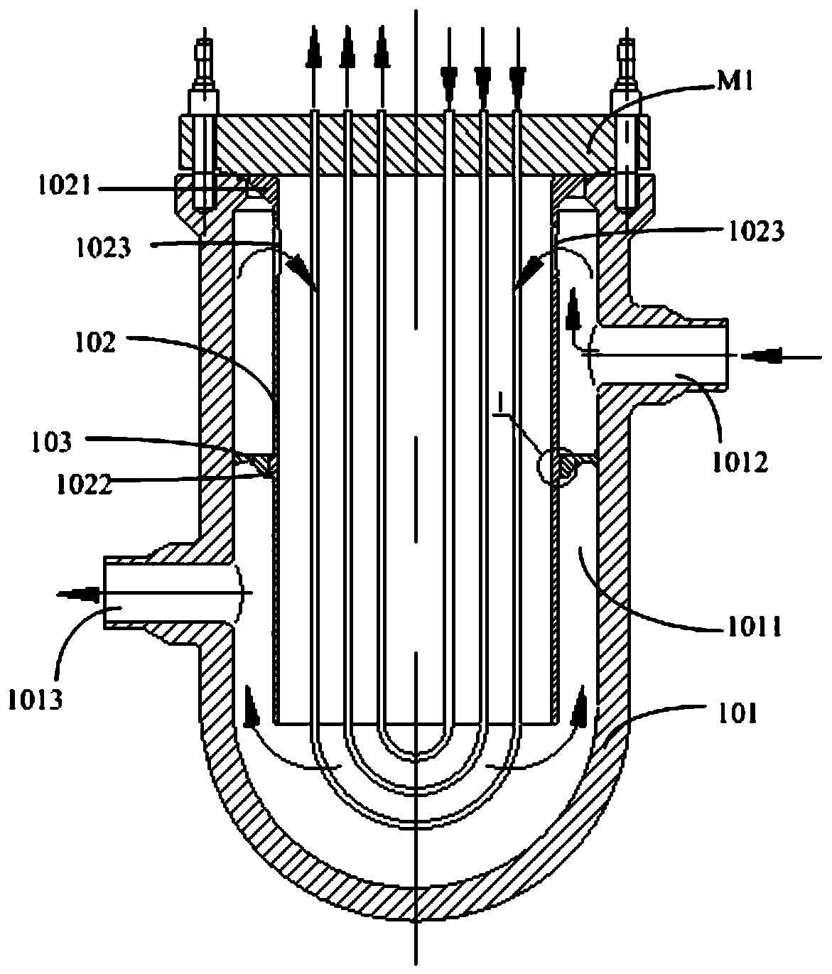
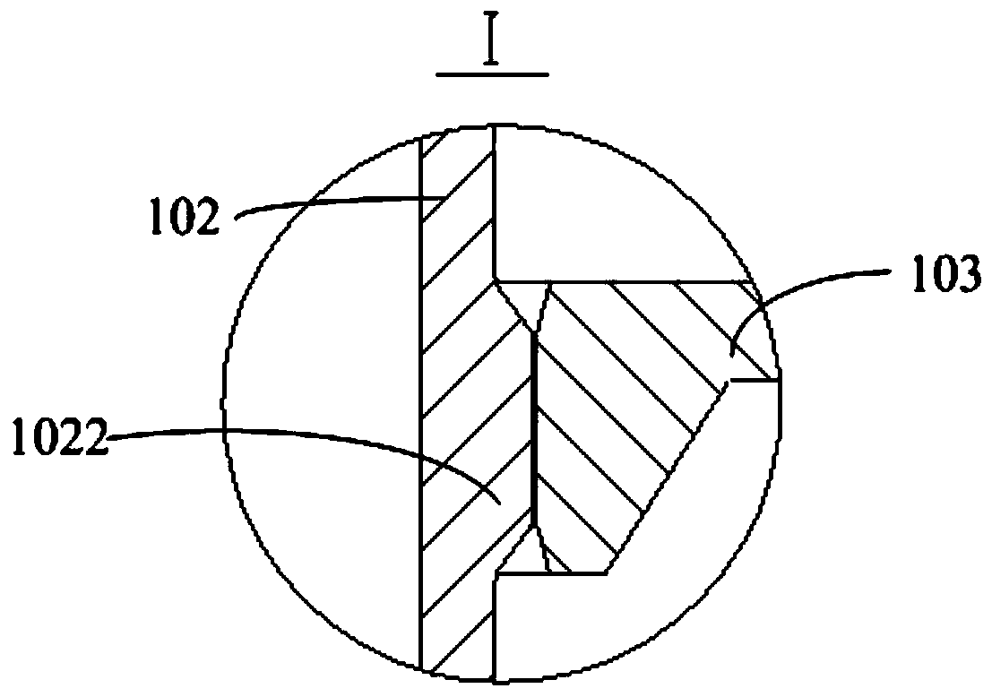
[0034] Such as figure 1 with figure 2 As shown, in Embodiment 1 of the present invention, a self-tightening flow channel sealing structure is provided, which is arranged inside the equipment or pipeline, including a housing 101, a sleeve 102 and a partition 103; wherein,

[0035] The casing 101 is fixed to a preset support platform (not shown) on the equipment or pipeline through the cover plate M1, on which a cavity 1011, an inlet 1012 for liquid (such as water, liquid metal, etc.) The discharge outlet 1013; wherein, the cavity 1011 is closed or has a hollow cavity with an opening facing the cover M1; the inlet 1012 is arranged close to the cover M1, and passes through the side wall of the housing 101 to communicate with the cavity 1011; The outlet 1013 is set...


PUM


Abstract

The invention provides a self tightening flow passage sealing structure. The self tightening flow passage sealing structure is arranged inside equipment or a pipeline and comprises a shell, a sleeve and a baffle; the shell is fixed on a support platform through a cover plate and is provided with a cavity, an inlet and an outlet, and both the inlet and the outlet communicate with the cavity; the sleeve is hollow tubular and is fixed on the cavity, a gap is formed between the sleeve and the cavity through a flanging provided by the outer wall, and the outer wall of the sleeve is provided with aboss and a guide hole; the baffle is annular, sleeves the sleeve, and is arranged in the gap, the outer ring is fixed on the inner wall of the cavity, and the inner ring is connected with the boss ina gap; and the thermal expansion coefficient of the sleeve is different from that of the shell and/or the baffle, so that the sleeve, the shell and/or the baffle are heated to expand to generate the thermal expansion difference when heated liquid flows in the sleeve, the shell and/or the baffle, and the sealing effect is achieved by the relative extrusion of the boss and the baffle. The self tightening flow passage sealing structure uses the thermal expansion characteristic of materials to seal, so that the structure is simpler, the reliability is higher, the service life is longer, and the manufacturing difficulty and the manufacturing cost are reduced without regular maintenance.

Description

technical field [0001] The invention relates to the technical field of equipment and pipeline sealing, in particular to a self-tightening flow channel sealing structure. Background technique [0002] At present, equipment and pipelines in nuclear power, petrochemical and other industries usually use metal sealing rings, gaskets and other sealing structures. When the liquid flows inside, it is very corrosive to this type of sealing structure, and it is easier to reduce the service life of this type of sealing structure. Contents of the invention [0003] The technical problem to be solved by the embodiments of the present invention is to provide a self-tightening flow channel sealing structure, which uses the thermal expansion characteristics of the material for sealing, so that the structure is simpler, the reliability is high, and the service life is long, and no regular maintenance is required. Manufacturing difficulty and manufacturing cost are reduced. [0004] In or...

Claims


Application Information

Patent Timeline
Patent Type & Authority Applications(China)
IPC IPC(8): F16L51/00
CPCF16L51/00
Inventor 李诚唐叔建路广遥刘青松叶亮周建明刘强韩万富芮旻吴凤岐周国丰董超群赵月扬秦小明刘志斌李权彰苏晓炜乔建毅
Owner CHINA NUCLEAR POWER TECH RES INST CO LTD
Why Eureka
Try Eureka