Ion wind heat dissipation device and heat dissipation method thereof

A heat sink, ion wind technology, applied in cooling/ventilation/heating transformation, electrical components, electrical equipment structural parts, etc., to achieve the effect of simple structure and small volume

Active Publication Date: 2019-10-15
XI AN JIAOTONG UNIV
View PDF3 Cites 2 Cited by
  • Summary
  • Abstract
  • Description
  • Claims
  • Application Information

AI Technical Summary

Problems solved by technology

[0005] In view of the above problems, in order to change the existing heat dissipation method, the present invention especially adopts a micro-structure ion wind heat dissipation method with simple structure, small and compact, zero noise and good cooling effect to overcome the defects in the prior art and provide better heat radiation

Method used


Image

  • Ion wind heat dissipation device and heat dissipation method thereof
  • Ion wind heat dissipation device and heat dissipation method thereof
  • Ion wind heat dissipation device and heat dissipation method thereof

Examples


no. 1 Embodiment approach

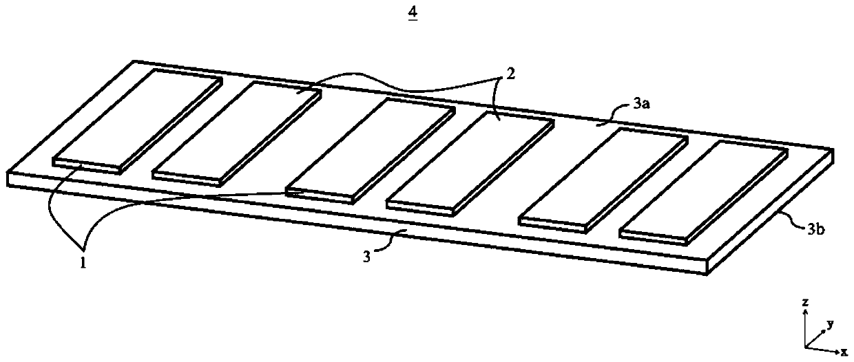
[0060] figure 1 It is a perspective view schematically showing the microstructure type ion wind heat sink 4 according to the first embodiment of the present disclosure.

[0061] The microstructured ionic wind cooling device 4 includes a microstructured ionic wind generating module and a base 3; wherein, the microstructured ionic wind generating module is composed of a number of unipolar microstructured ionic wind generating units.

[0062] The microstructured ion wind generating unit includes a microstructured high voltage electrode 1 and a microstructured ground electrode 2 .

[0063] When the microstructured ion wind cooling device 4 is working, the microstructured high-voltage electrode 1 is powered by a high-voltage power supply, and the microstructured grounding electrode 2 is grounded. A strong electric field will be generated in the area between the microstructured high-voltage electrode 1 and the microstructured grounding electrode 2 . Under the action of a strong ele...

no. 2 Embodiment approach

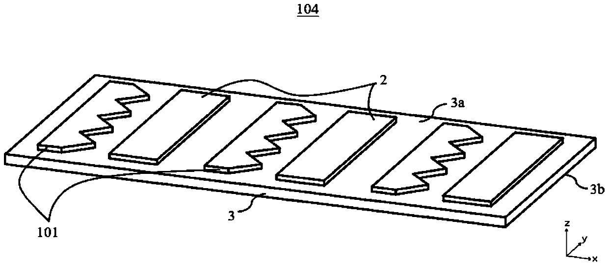
[0075] figure 2 It is a perspective view schematically showing the microstructure type ionic wind heat sink 104 according to the second embodiment of the present disclosure.

[0076] The only difference between the microstructured ionic wind heat sink 104 and the microstructured ionic wind heat sink 4 of the first embodiment lies in the shape of the microstructured high voltage electrodes. Specifically, as follows.

[0077] The microstructured high voltage electrode 101 is configured in a shape in which the distance from the microstructured ground electrode 2 varies. For example, the planar shape of the microstructure high-voltage electrode 101 near the downstream side of the ion wind is zigzag, so the electrode spacing of the microstructure ion wind generating unit changes along the width direction (y direction).

[0078] In addition, the size and number of the sawtooth structures of the microstructure high voltage electrode 101 can be properly adjusted according to heat d...

no. 3 Embodiment approach

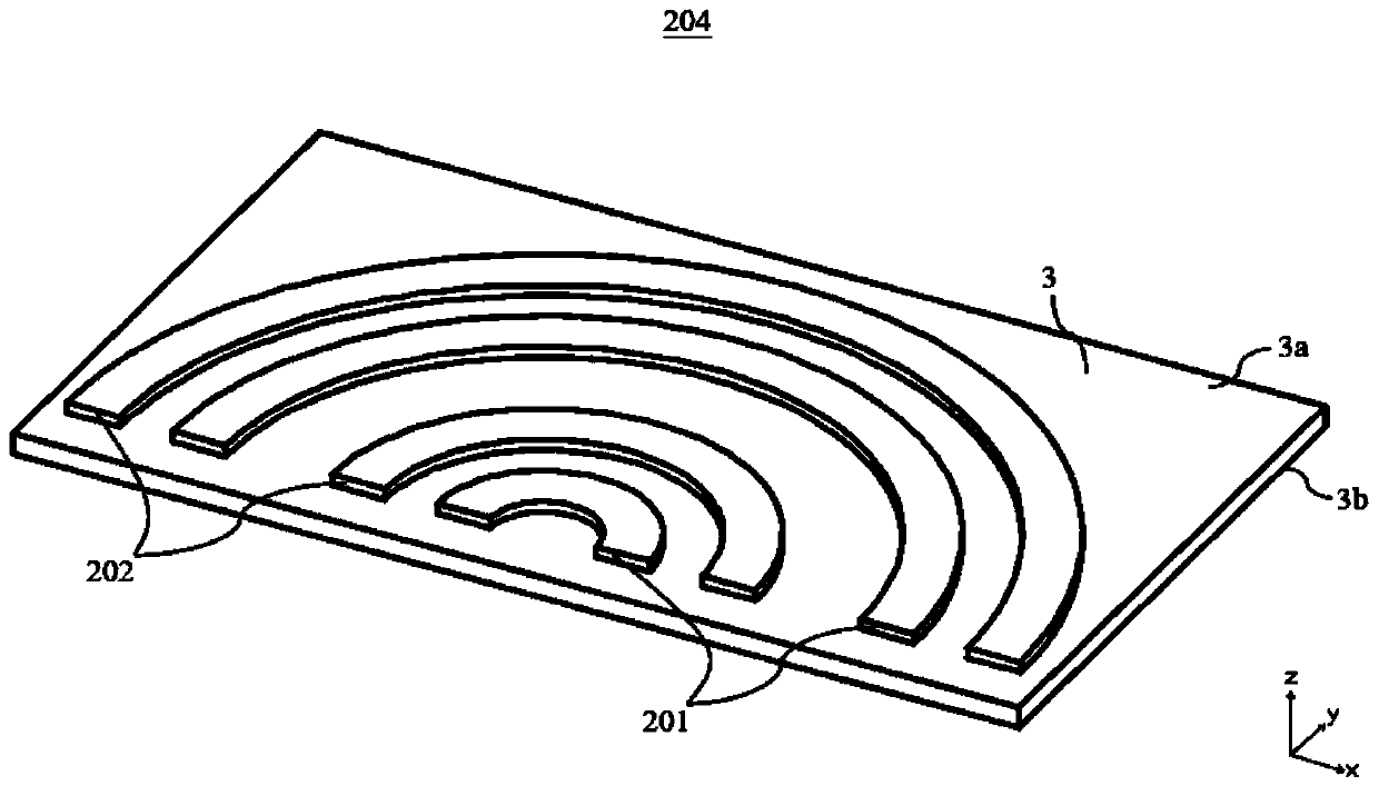
[0082] image 3 It is a perspective view schematically showing the microstructure type ionic wind heat sink 204 according to the third embodiment of the present disclosure.

[0083] The only difference between the microstructured ionic wind heat sink 204 and the microstructured ionic wind heat sink 4 of the first embodiment lies in the shape of the microstructured high voltage electrode and the microstructured ground electrode. Specifically, as follows.

[0084] The plane shapes of the microstructure high voltage electrode 201 and the microstructure ground electrode 202 are arched. In addition, the width of these electrodes in the radial direction can either remain the same or vary along the circumferential direction.

[0085] In addition, the width of the microstructure high voltage electrode 201 and the microstructure ground electrode 202 in the radial direction and the circumferential angle of the electrodes can be properly adjusted according to the size of the space and ...


PUM


Abstract

The invention discloses an ion wind heat dissipation device and a heat dissipation method thereof. The device comprises a substrate and an ion wind generation module, wherein the substrate comprises an upper surface and a lower surface used for being attached to an object to be subject to heat dissipation; the ion wind generation module comprises at least one ion wind generation unit, the at leastone ion wind generation unit can be laid on the upper surface in an overlapping mode, each of the at least one ion wind generation unit comprises a microstructure high-voltage electrode and a microstructure grounding electrode, wherein the bottom surface of the microstructure high-voltage electrode is flatly paved on the upper surface, the microstructure high-voltage electrode is supplied with power by a high-voltage power supply, the microstructure grounding electrode is grounded, the microstructure grounding electrode and the microstructure high-voltage electrode are oppositely arranged toform an ion air channel between the microstructure grounding electrode and the microstructure high-voltage electrode, the microstructure grounding electrode is located at the position of the downstream side of the ion air channel relative to the microstructure high-voltage electrode, and the sizes of the bottom surfaces of the microstructure high-voltage electrode and the microstructure groundingelectrode are respectively far larger than sizes of other surfaces of the microstructure high-voltage electrode and the microstructure grounding electrode.

Description

technical field [0001] The invention relates to the technical field of heat dissipation of electronic equipment, in particular to an ion wind heat dissipation device and a method thereof. Background technique [0002] With the development of technology, the working capacity of electronic equipment has been continuously improved, which has led to an increase in heat production. However, the miniaturization of equipment has greatly increased the power density of electronic equipment, but the cooling area has been severely reduced. Performance and service life have an important impact, therefore, electronic cooling technology has become an important factor restricting the development of electronic equipment. [0003] The traditional heat dissipation method is mainly a heat sink that combines a fan and a fin heat sink. The motor rotates to drive the fan to drive the air to exchange heat with the fins to achieve the effect of heat dissipation. However, this type of mechanical he...

Claims


Application Information

Patent Timeline
Patent Type & Authority Applications(China)
IPC IPC(8): H05K7/20
CPCH05K7/20136
Inventor 张剑飞张德伟屈治国
Owner XI AN JIAOTONG UNIV
Why Eureka
Try Eureka