Cooking utensil with pressure control structure

A technology for cooking utensils and containers, which is applied to cooking utensils, pressure cookers, household utensils, etc., and can solve problems such as unsatisfactory heating uniformity of food

Pending Publication Date: 2019-10-18
拓浦精工智能制造(邵阳)有限公司
1 Cites 4 Cited by

AI-Extracted Technical Summary

Problems solved by technology

But the inventor finds through many studies that the heating uni...

Abstract

The invention discloses a cooking utensil with a pressure control structure. The cooking utensil comprises a container for containing food and a cover body arranged on the container in a covering manner; the cooking utensil is characterized in that a first pressure release valve and a second pressure release valve are arranged on the cover body; the first pressure release valve is used for maintaining a working internal pressure in the container to be in a high-pressure environment; the first pressure release valve is arranged to act and release gas in the container to an external space when the working internal pressure in the container is higher than a pressure threshold value, so that the high-pressure working environment is maintained in the container, wherein the pressure threshold value is higher than the atmospheric pressure of the external space; the second pressure release valve is used for releasing the gas in the containing container to the external space; and under the synergistic effect of the first pressure release valve and the second pressure release valve, liquid in the container can be bumped, so that the food in the container can be stirred to be uniformly heated, and the taste is optimized.

Application Domain

Pressure-cookers

Technology Topic

Pressure thresholdInternal pressure +6

Image

  • Cooking utensil with pressure control structure
  • Cooking utensil with pressure control structure

Examples

  • Experimental program(1)

Example Embodiment

[0020] The structure of a cooking appliance with a pressure control structure applying the technical solution of the present invention will be further described below in conjunction with the accompanying drawings.
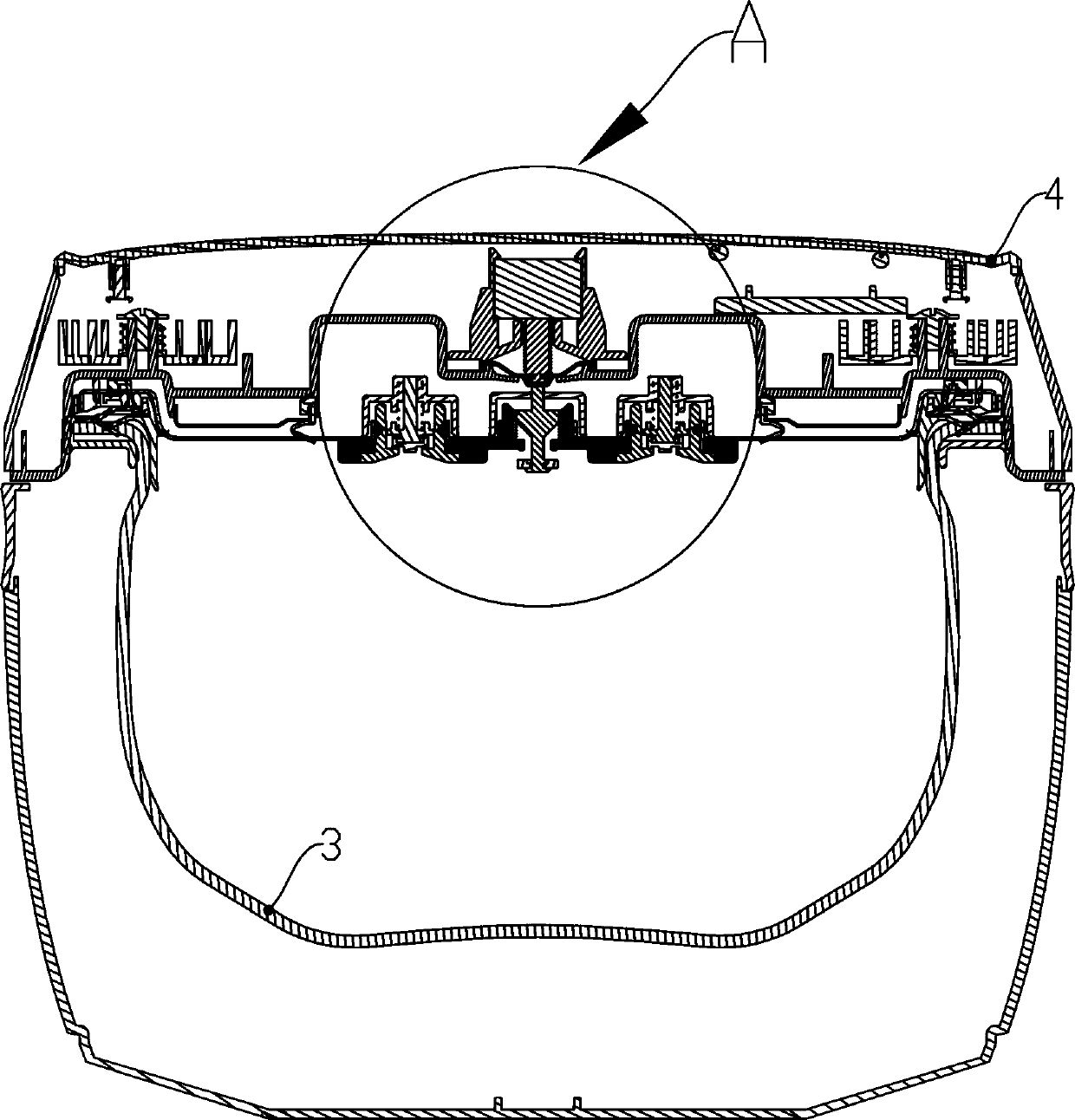
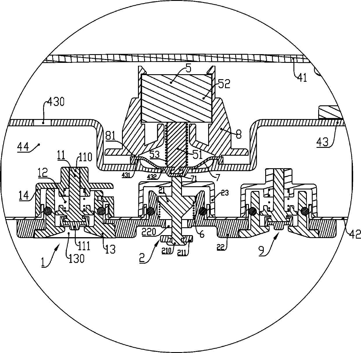
[0021] Such as figure 1 with figure 2 As shown, a cooking appliance with a pressure control structure includes a container 3 for holding food and a cover 4 covered on the container 3. A first pressure relief valve 1 and a second pressure relief valve 2 are provided on the cover body 4. The first pressure relief valve 1 is used to maintain the working internal pressure in the container 3 in a high-pressure environment. The first pressure relief valve 1 is arranged so that when the working internal pressure in the container 3 is higher than the pressure threshold P 0 Acts and releases the gas in the container 3 to the external space so that the high-pressure working environment is maintained in the container 3, and the pressure threshold is higher than the atmospheric pressure of the external space; the second pressure relief valve 2 For releasing the gas in the container 3 to the external space, the second pressure relief valve 2 includes a second pressure relief hole 220 that can release the gas in the container 3 and can block or open the The second valve stem 21 of the second pressure relief hole 220 also includes a valve stem driver. The valve stem driver can not only drive the second valve stem 21 to move and block the second pressure relief hole 220, but also drive The second valve stem 21 moves to open the second pressure relief hole 220, and the valve stem driver is arranged to respond to the container when the container 3 is maintained in the high-pressure working environment. 3 and when the operating temperature is higher than the temperature threshold T 0 When driving the second valve rod 21 to move and release the gas in the container 3 to the outside space so as to cause the liquid in the container 3 to collapse and boil, the temperature threshold T 0 The temperature is greater than the boiling point of the liquid at the atmospheric pressure of the outer space. The cover 4 is also provided with a controller (not shown in the figure) and a temperature sensor (not shown in the figure), and the valve stem driver and the temperature sensor are respectively signally connected to the controller.
[0022] Attached below figure 2 First, the structure of the first pressure relief valve 1 will be further explained. The cover body 4 includes an outer cover body 41, an inner cover body 42, and an isolation cover body 43 disposed between the outer cover body 41 and the inner cover body 42. The isolation cover body 43 and the inner cover body A gas collection cavity 44 is formed between 42. An exhaust channel 430 communicating with the external space is provided on the cavity side wall of the gas collection cavity 44. The first pressure relief valve 1 includes a first valve seat 13 and a first valve cover 14. The first valve cover 14 is arranged in the gas collection chamber 44, and the upper part of the first valve seat 13 passes through the inner cover body 42 from bottom to top to be fastened to the first valve cover 14. The lower part of the first valve seat 13 is clamped under the inner cover body 42, specifically, clamped on the lower part of the second valve seat 22 to be discussed below. The first pressure relief valve 1 also includes a first pressure relief hole 130 capable of releasing the gas in the container 3, a first valve stem 11 capable of blocking or opening the first pressure relief hole 130, and The first valve rod driving spring 12 that drives the first valve rod 11 to move. The first pressure relief hole 130 is provided on the first valve seat 13 and communicates with the gas collection chamber 44 and the container 3. The first valve rod 11 includes a first valve main rod 110 and a first sealing member 111 arranged at the rear end of the first valve main rod 110. The first valve cover 14 is provided with a first connecting hole portion (which is blocked by the first valve main rod 110 in the figure and is not marked), and the top end of the first valve main rod 110 is vertically movable. On the first connection hole. Wherein the first valve stem 11 is used for the working internal pressure in the container 3 to be lower than the pressure threshold P 0 When the second valve stem drive spring 6 is driven to move and block the first pressure relief hole 130; the first valve stem 11 is also used for high working internal pressure in the container 3 At the pressure threshold P 0 At this time, under the action of the working internal pressure, it overcomes the resistance given by the second valve stem drive spring 6 and moves to open the first pressure relief hole 130. According to the above solution, the first pressure relief valve 1 can act in response to changes in the working internal pressure in the container 3, so that a high-pressure working environment can be maintained in the container 3. A third pressure relief valve 9 is also provided on the cover body 4. The third pressure relief valve 9 has the same structure as the first pressure relief valve 1, except that the third pressure relief valve 9 is The operating pressure opened in response is greater than the pressure threshold P 0 When the first pressure relief valve 1 fails to relieve pressure, it plays a role of pressure relief.
[0023] Such as figure 2 As shown, the second pressure relief valve 2 further includes a second valve seat 22 and a second valve cover 23. The second valve cover 23 is arranged in the gas collection chamber 44, and the upper part of the second valve seat 22 passes through the inner cover body 42 from bottom to top to be fastened to the second valve cover 23, The lower part of the second valve seat 22 is clamped under the inner cover 42. The second pressure relief hole 220 is provided on the second valve seat 22. The second valve rod 21 includes a second valve main rod 210 and a second sealing member 211 provided at the rear end of the second valve main rod 210. The second valve cover 23 is provided with a second connecting hole portion (which is blocked by the second valve main rod 210 in the figure and is not marked), and the top end of the second valve main rod 210 is vertically movable. On the second connecting hole.
[0024] The valve stem driver may be an independent functional module capable of independently completing the opening and blocking actions of the second valve stem 21, for example, a functional module composed of a motor, a gear, and a rack. In this embodiment, the valve stem driver is two independent functional modules. Specifically, the valve stem driver includes an opening that can drive the second valve stem 21 to move and open the second pressure relief hole 220. The driver 5 and the driver 6 for blocking that can drive the second valve rod 21 to move and block the second pressure relief hole 220 are used. The opening driver 5 includes a power output shaft 51 for driving the second valve stem 21 to move, an electromagnet 52 capable of driving the power output shaft 51 to move, and an output shaft drive spring 53. Wherein, the output shaft drive spring 53 is used to drive the second valve stem 21 to move to open the second pressure relief hole 220 through the power output shaft 51 when the electromagnet 52 is in a de-energized state. The electromagnet 52 is used to drive the power output shaft 51 to overcome the resistance given by the output shaft drive spring 53 to move away from the second valve stem 21 in its energized state. The opening driver 5 is arranged outside the gas collection chamber 44, and the isolation cover 43 is provided with an escape hole 432 for avoiding the power output shaft 51. It also includes an elastic sealing film 7, which is used to block the escape hole 432, but does not prevent the power output shaft 51 from passing through the escape hole 432 to drive the second valve stem 21 to move . In this way, the use of the elastic sealing film 7 can reduce the steam discharged from the container 3 being sprayed onto the opening driver 5 and causing damage to the opening driver 5, effectively protecting the opening driver 5. Further, a protrusion 71 is provided in the middle of the elastic sealing film 7, a T-shaped hole is provided on the protrusion 71, and the head of the power output shaft 51 is T-shaped and is inserted into Inside the T-shaped hole. The cover 4 is further provided with a fixing bracket 8, the fixing bracket 8 is arranged outside the gas collection chamber 44, and the opening driver 5 is installed on the fixing bracket 8. An upper pressure ring 81 is provided on the fixing bracket 8, a lower pressure ring 431 is also provided on the cavity side wall of the gas collection chamber 44, and the escape hole 432 is provided in the lower pressure ring 431. In the inner ring area, the outer edge of the elastic sealing film 7 is clamped between the upper pressure ring 81 and the lower pressure ring 431. In this way, the elastic sealing film 7 can be easily fixed.
[0025] Such as figure 2 As shown, the plugging driver 6 is a second valve stem drive spring 6, and the second valve stem drive spring 6 is used when the second valve stem 21 loses the driving force of the opening driver 5 , Drive the second valve stem 21 to move and block the second pressure relief hole 220. In this way, the opening driver 5 can drive the second valve stem 21 to overcome the resistance of the second valve stem drive spring 6 to move to open the second pressure relief hole 220, and when the opening driver 5 cancels the application When the force on the second valve stem 21 is applied, the second valve stem drive spring 6 drives the second valve stem 21 to move and block the second pressure relief hole 220.
[0026] According to the above technical solution, the pressure control process of the cooking appliance is as follows: the cooking appliance is used for cooking under normal pressure, and the first pressure relief valve 1 is in a closed state at the beginning of cooking; the controller does not Provide an electrical signal to the electromagnet 52, that is, the electromagnet 52 is in a de-energized state, and the output shaft drive spring 53 drives the power output shaft 51 to move downward through the elastic sealing film 7. The power output shaft 51 pushes the second valve stem 21 and also moves downward to open the second pressure relief hole 220. Start heating. When the liquid in the container 3 is in a fully boiling state, the working temperature of the container 3 reaches 100°C, and the temperature sensor transmits the temperature signal sensed at this time to the The controller provides an electrical signal to the electromagnet 52 in response to the temperature signal, and the electromagnet 52 is in an energized state. The electromagnet 52 overcomes the resistance of the output shaft drive spring 53 to drive the power output shaft 51 to move upward so that the power output shaft 51 leaves the second valve stem 21. The second valve stem 21 moves upward under the action of the second valve stem drive spring 6 to reset and re-block the second pressure relief hole 220. Subsequently, the working pressure of the container 3 will gradually increase to the pressure threshold P because the steam generated by boiling cannot be discharged. 0 For example, 20kpa. When the working pressure of the container 3 is greater than 20kpa, the first pressure relief valve 1 is opened to release the internal pressure, and when the working pressure of the container 3 is less than 20kpa, the first pressure relief valve 1 is closed , So that the working pressure of the container 3 is maintained at about 20kpa, which causes the boiling point of the liquid in the container 3 to rise to the temperature threshold T 0 For example, 105°C. The temperature sensor transmits the temperature signal sensed at this time to the controller, and the controller stops providing electrical signals to the electromagnet 52 in response to the temperature signal, and the electromagnet 52 switches to de-energization State, causing the second pressure relief valve 2 to switch to the open state. A large amount of steam is discharged from the second pressure relief hole 220, the working pressure of the container 3 drops rapidly, and the boiling point temperature is also reduced to 100°C, causing the liquid in the container 3 to become a superheated liquid state. Bumping phenomenon. Solid foods such as rice grains undergo a violent physical change process such as bump boiling. Compared with traditional cooking methods, rice is heated more evenly. Subsequently, when the operating temperature is lower than the temperature threshold T 0 For example, at 95°, the valve stem driver drives the second valve stem 21 to move to re-block the second pressure relief hole 220; or when the second pressure relief valve 2 continues to relieve pressure for a specific period of time, such as 20s Afterwards, the valve stem driver drives the second valve stem 21 to move to re-block the second pressure relief hole 220, thereby facilitating the restoration of the high-pressure working environment in the container 3, or further down cycle Prepare for collapse.
[0027] According to the above technical solution, compared with the existing patent CN03149178.2, the beneficial technical effects of the present invention are: firstly, due to the synergistic effect of the first pressure relief valve 1 and the second pressure relief valve 2, let The liquid in the container 3 will collapse and boil, so that the food in the container 3 can be stirred so that the food is evenly heated and the taste is optimized. In addition, because the valve stem driver can not only drive the second valve stem 21 to move to block the second pressure relief hole 220, but also drive the second valve stem 21 to move to open the second pressure relief hole 220, In this way, the second valve stem 21 does not need to rely on its own weight to block the second pressure relief hole 220 like the gravity ball in patent CN03149178.2, and get rid of the gravity ball and pressure relief in patent CN03149178.2 The hole diameter has a dilemma of proportional relationship. In this way, the aperture size of the second pressure relief hole 220 has very little effect on the volume, weight, and manufacturing cost of the second valve stem 21. Even if the second pressure relief hole 220 with a large diameter is configured, it will not cause the The cost of the pressure control structure increases sharply, and the second valve stem 21 can generally be made of low-cost plastic, which is beneficial to further reduce the pressure control structure. Based on the above, the pore size of the second pressure relief hole 220 can be set reasonably to optimize the boiling effect.

PUM

no PUM

Description & Claims & Application Information

We can also present the details of the Description, Claims and Application information to help users get a comprehensive understanding of the technical details of the patent, such as background art, summary of invention, brief description of drawings, description of embodiments, and other original content. On the other hand, users can also determine the specific scope of protection of the technology through the list of claims; as well as understand the changes in the life cycle of the technology with the presentation of the patent timeline. Login to view more.
Why Eureka
Try Eureka