
An Electronic Buzzer Pin Calibration and Centering Mechanism

A technology of centering mechanism and correction mechanism, which is applied in metal processing equipment, metal processing, manufacturing tools, etc.

Active Publication Date: 2021-05-18
JIANGSU UNIV OF TECH
View PDF10 Cites 0 Cited by
  • Summary
  • Abstract
  • Description
  • Claims
  • Application Information

AI Technical Summary

Problems solved by technology

[0005] The purpose of the present invention is to solve the technical problems of electronic buzzer pin calibration and automatic production of pin connection and sound hole alignment

Method used


Image

  • An Electronic Buzzer Pin Calibration and Centering Mechanism
  • An Electronic Buzzer Pin Calibration and Centering Mechanism
  • An Electronic Buzzer Pin Calibration and Centering Mechanism

Examples


Embodiment Construction

[0040] like Figure 4 As shown, an electronic buzzer pin correction and centering mechanism is characterized in that it includes a feeding mechanism, a material introduction mechanism, a pin correction mechanism, a centering mechanism and a base 102:

[0041] like Image 6 As shown, the feeding mechanism includes an electromagnetic vibration plate 201, the electromagnetic vibration plate is placed on the support frame 103, the electromagnetic vibration plate 201 is connected with a material guide groove 204, and the material guide groove 204 is installed on the linear electromagnetic vibration On the device 202, the material guide groove 204 is provided with a material guide piece 203 for guiding the direction of the buzzer pin, and the material guide piece 203 is fixed on the material guide groove 204 by a fixing clip 207, and the material guide groove The end of 204 away from the electromagnetic vibrating disk 201 is a material guide outlet, the end of the material guide gr...


PUM


Abstract

The invention discloses a pin correction and centering mechanism of an electronic buzzer, which belongs to the technical field of electronic component processing and includes a feeding mechanism, a material introduction mechanism, a pin correction mechanism, a centering mechanism and a base. The feeding mechanism includes an electromagnetic A vibrating plate, the electromagnetic vibrating plate is connected with a material guide groove, and the material guide groove is installed on a linear electromagnetic vibrator; the material guiding mechanism includes a lifting cylinder and a material pulling cylinder, and the material pulling cylinder is provided with a material pulling cylinder. sheet; the pin correction mechanism includes two opposite clamping cylinders, and the sides of the two clamping cylinders are respectively provided with correction fixtures; the centering mechanism includes a stepping motor, and the stepping motor It is connected with positive and negative lead screws, and the positive and negative lead screws drive the two centering fixtures to move relative to each other. The invention realizes the automatic production of buzzer pin correction and centering, completely replaces manual work, has high correction and centering accuracy, good product consistency, high production efficiency, and has wide application prospects.

Description

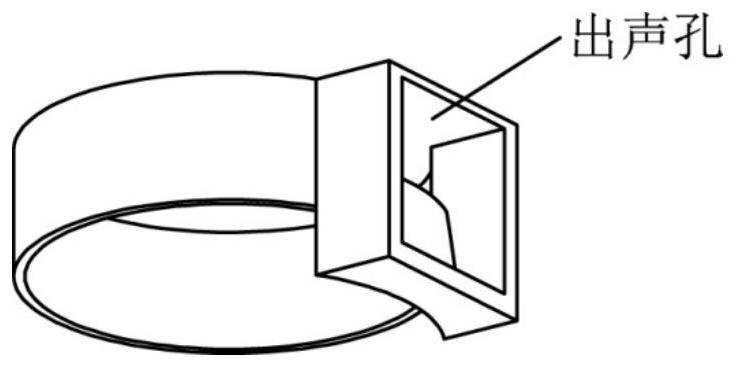
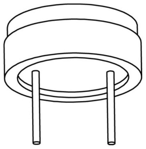
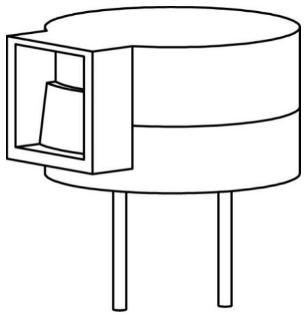
technical field [0001] The invention relates to the technical field of processing electronic components, in particular to a pin correction and centering mechanism of an electronic buzzer. Background technique [0002] Buzzer is an electronic sounder, which is widely used in computers, alarms, electronic toys, game consoles, printers, repeaters, automotive electronic equipment, telephones, timers and other electronic products as sounding devices. The existing production process is the buzzer pin socket ( figure 2 ) and upper shell ( figure 1 ) are produced separately and then assembled ( image 3 ), where the pins on the pin base are often corrected mechanically, but the assembly process is often done manually for subsequent automated assembly of the buzzer. [0003] Chinese patent 201710995843.3 discloses "a pin correction mechanism for electronic components", including a correction component, a fixed component, a sliding component, a foot spacing widening mechanism and ...

Claims


Application Information

Patent Timeline
Patent Type & Authority Patents(China)
IPC IPC(8): B23P19/10B21F1/02
CPCB21F1/02B23P19/10
Inventor 孙奎洲孙小艺刘志华
Owner JIANGSU UNIV OF TECH
Learn More