Clamping device for installation of linear motor magnet

A technology of linear motors and magnets, applied in the direction of chucks, manipulators, program-controlled manipulators, etc., can solve problems such as positioning deviation and troublesome installation, and achieve the effects of easy manufacturing, simple installation, and high installation efficiency

Active Publication Date: 2019-10-18
深圳市锐健电子有限公司
View PDF6 Cites 2 Cited by
  • Summary
  • Abstract
  • Description
  • Claims
  • Application Information

AI Technical Summary

Problems solved by technology

[0003] In order to overcome the existing disadvantages that the magnets of linear motors are installed manually by hand, the mutual repulsion or attraction between the magnets will easily lead to positioning deviation, requiring staff to continuously adjust the position of the magnets, and the disadvantage of troublesome installation. The technical problem to be solved by the present invention is to provide a clamping device for installing linear motor magnets with precise positioning, no need for staff to continuously adjust the position of the magnet, and simple installation

Method used


Image

  • Clamping device for installation of linear motor magnet
  • Clamping device for installation of linear motor magnet
  • Clamping device for installation of linear motor magnet

Examples


Embodiment 1

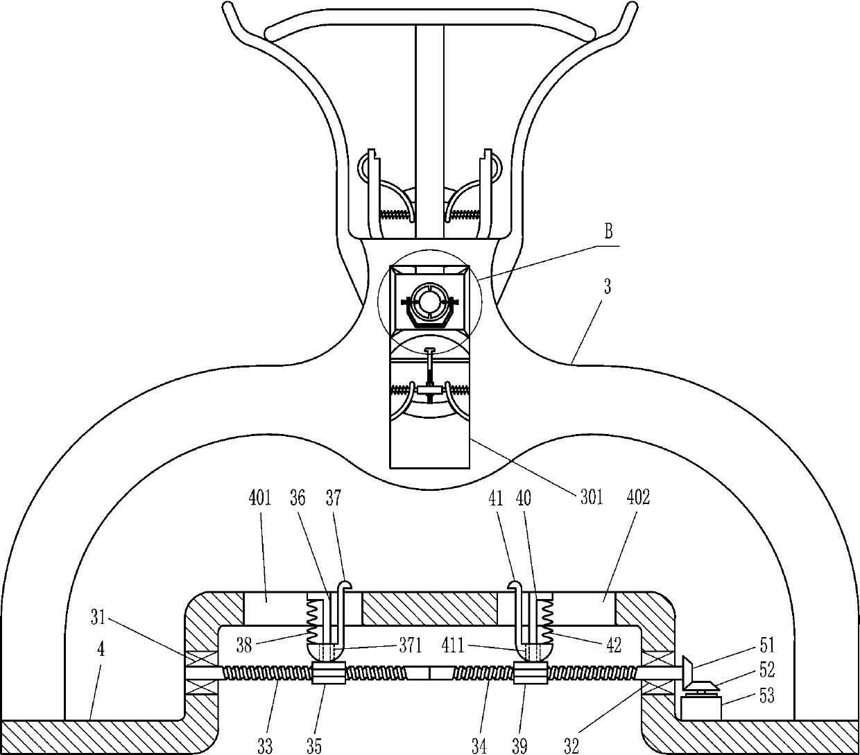
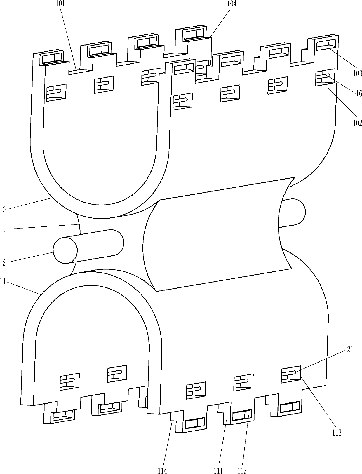
[0018] A clamping device for mounting the magnet of the linear motor 53, such as Figure 1-3 As shown, it includes a large connecting block 1, a large rotating shaft 2, a large arc-shaped frame 3, a workbench 4, a large rectangular plate 5, a large lifting rod 6, a large arc-shaped extrusion plate 7, and a large arc-shaped leaf spring 8 , large bearing 9, first large U-shaped plate 10, second large U-shaped plate 11, extrusion device 12, first limit plate 13, first connecting rod 14, first arc splint 15, first small rotating Shaft 16, the first spring 17, the second limiting plate 18, the second connecting rod 19, the second arc splint 20, the second small rotating shaft 21 and the second spring 22, the middle part of the large connecting block 1 is embedded with a large Rotary shaft 2, the both sides of large connecting block 1 are provided with large arc frame 3 symmetrically front and back, the middle part of large arc frame 3 has the large rectangular groove 301 that runs ...

Embodiment 2

[0020] A clamping device for mounting the magnet of the linear motor 53, such as Figure 1-3As shown, it includes a large connecting block 1, a large rotating shaft 2, a large arc-shaped frame 3, a workbench 4, a large rectangular plate 5, a large lifting rod 6, a large arc-shaped extrusion plate 7, and a large arc-shaped leaf spring 8 , large bearing 9, first large U-shaped plate 10, second large U-shaped plate 11, extrusion device 12, first limit plate 13, first connecting rod 14, first arc splint 15, first small rotating Shaft 16, the first spring 17, the second limiting plate 18, the second connecting rod 19, the second arc splint 20, the second small rotating shaft 21 and the second spring 22, the middle part of the large connecting block 1 is embedded with a large Rotary shaft 2, the both sides of large connecting block 1 are provided with large arc frame 3 symmetrically front and back, the middle part of large arc frame 3 has the large rectangular groove 301 that runs t...

Embodiment 3

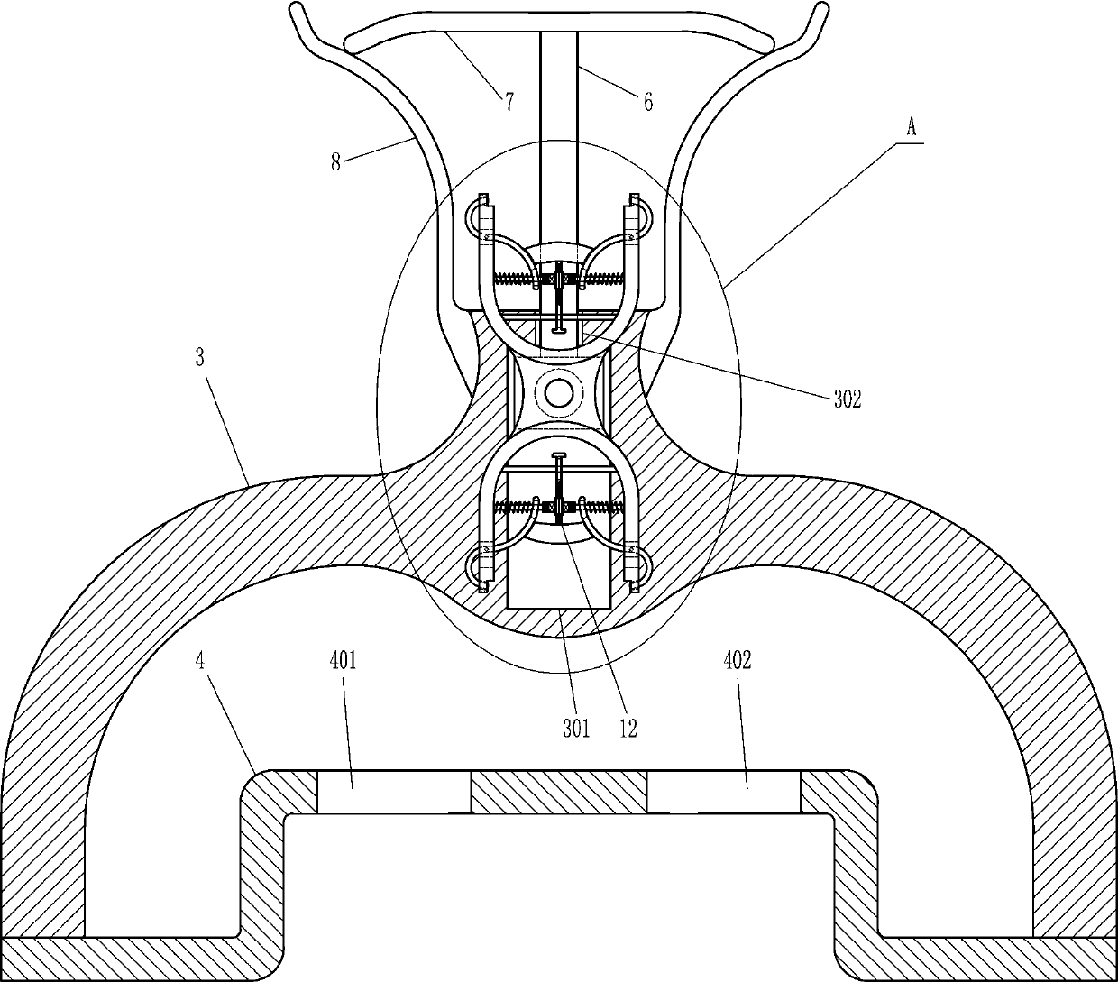
[0023] A clamping device for mounting the magnet of the linear motor 53, such as Figure 1-4As shown, it includes a large connecting block 1, a large rotating shaft 2, a large arc-shaped frame 3, a workbench 4, a large rectangular plate 5, a large lifting rod 6, a large arc-shaped extrusion plate 7, and a large arc-shaped leaf spring 8 , large bearing 9, first large U-shaped plate 10, second large U-shaped plate 11, extrusion device 12, first limit plate 13, first connecting rod 14, first arc splint 15, first small rotating Shaft 16, the first spring 17, the second limiting plate 18, the second connecting rod 19, the second arc splint 20, the second small rotating shaft 21 and the second spring 22, the middle part of the large connecting block 1 is embedded with a large Rotary shaft 2, the both sides of large connecting block 1 are provided with large arc frame 3 symmetrically front and back, the middle part of large arc frame 3 has the large rectangular groove 301 that runs t...


PUM


Abstract

The invention relates to a clamping device, in particular to a clamping device for installation of a linear motor magnet. The clamping device for installation of the linear motor magnet is provided for achieving the technical effects that locating is accurate, working staff do not need to adjust the magnet continuously and installation is easy. The clamping device for installation of the linear motor magnet, provided by the invention, comprises a big connecting block, a big rotary shaft and the like. The big rotary shaft is embedded in the middle portion of the big connecting block. A big arc-shaped rack is arranged on the two sides of the big connecting block in front-back symmetry. The upper end of the big arc-shaped rack is provided with a big lifting hole extending downwards. The big lifting hole is located over a big rectangular groove. The lower end of the big arc-shaped rack is fixedly connected with a working platform. The left side of the top of the working platform is provided with a vertical through left groove. A big rectangular plate is located in the big rectangular groove and is in sliding fit with the big rectangular groove. The top of the big rectangular plate is fixedly connected with a big lifting rod. The big lifting rod is slidably located in the big lifting hole. The clamping device for installation of the linear motor magnet is accurate in locating and high in installation efficiency.

Description

technical field [0001] The invention relates to a clamping device, in particular to a clamping device for installing a linear motor magnet. Background technique [0002] Linear motor is a kind of transmission device that directly converts electrical energy into linear motion mechanical energy without any intermediate conversion mechanism. It can be regarded as a rotary motor that is cut radially and developed into a plane. The linear motor is in the During the manufacturing process, it is necessary to install magnets of different polarities on the substrate at intervals. The existing magnets of the linear motor are installed manually, and the mutual repulsion or attraction between the magnets will easily lead to positioning deviations. The staff constantly adjusts the position of the magnet, and the installation is troublesome, which causes hidden dangers to the quality and application of the linear motor. Contents of the invention [0003] In order to overcome the existi...

Claims


Application Information

Patent Timeline
Patent Type & Authority Applications(China)
IPC IPC(8): B25J9/00B25J15/00B25J15/02
CPCB25J9/00B25J15/0253B25J15/0095
Inventor 陈聪
Owner 深圳市锐健电子有限公司
Why Eureka
Try Eureka