
Bonding device and method for base with annular groove and permanent magnet

A technology of annular groove and permanent magnet, applied in the manufacture of inductors/transformers/magnets, electrical components, circuits, etc., can solve the problems of high cost, long time consumption, low efficiency and so on

Active Publication Date: 2021-05-18
GUIZHOU RADIO & TV UNIV
View PDF13 Cites 0 Cited by
  • Summary
  • Abstract
  • Description
  • Claims
  • Application Information

AI Technical Summary

Problems solved by technology

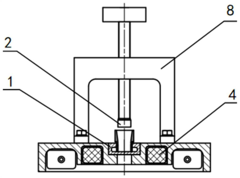
[0004] In view of this, the object of the present invention is to provide a bonding device and method for a base with an annular groove and a permanent magnet, aiming at solving the problems of high cost, low efficiency and long time consumption in the bonding of the two

Method used


Image

  • Bonding device and method for base with annular groove and permanent magnet
  • Bonding device and method for base with annular groove and permanent magnet
  • Bonding device and method for base with annular groove and permanent magnet

Examples


Embodiment Construction

[0026] Embodiments of the present invention are described below through specific examples, and those skilled in the art can easily understand other advantages and effects of the present invention from the content disclosed in this specification. The present invention can also be implemented or applied through other different specific implementation modes, and various modifications or changes can be made to the details in this specification based on different viewpoints and applications without departing from the spirit of the present invention. It should be noted that the diagrams provided in the following embodiments are only schematically illustrating the basic concept of the present invention, and the following embodiments and the features in the embodiments can be combined with each other in the case of no conflict.

[0027] Wherein, the accompanying drawings are for illustrative purposes only, and represent only schematic diagrams, rather than physical drawings, and should...


PUM


Abstract

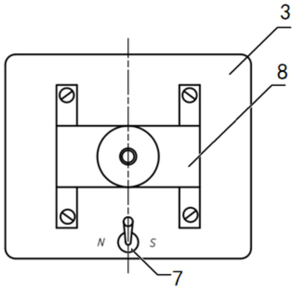
The invention belongs to the technical field of permanent magnet assembly, relates to a bonding device and method for a base with an annular groove and a permanent magnet, and aims to solve the problems of high cost, low efficiency and long consumed time in bonding of the base with the annular groove and the permanent magnet. The device comprises a pedestal, and the pedestal is provided with the base with the annular groove, a magnetic repulsion device used for releasing the polarity opposite to that of the permanent magnet and a lifting sealing mechanism used for enabling the permanent magnet to make contact with a groove bottom bonding face of the base with the annular groove. The magnetic repulsion device is composed of a coil, a power supply and a switch, and the coil surrounds the base with the annular groove and is connected with the power supply through the switch. The bonding device generates a magnetic field opposite to the polarity of the permanent magnet through the magnetic repulsion device so as to generate repulsive force to the permanent magnet, so that the phenomena that when the base with the annular groove is bonded with the permanent magnet, the permanent magnet collides with the base due to the magnetic force of the permanent magnet, so that the permanent magnet is chipped and cracked, can be avoided. When the current of the coil is disconnected, the bonding device loses the magnetic field, and the permanent magnet is quickly and accurately bonded with the base with the annular groove.

Description

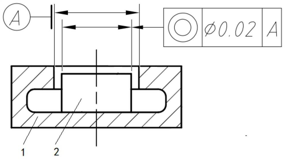
technical field [0001] The invention belongs to the technical field of permanent magnet assembly, and in particular relates to a bonding device and method for a base with an annular groove and a permanent magnet. Background technique [0002] In engineering practice, it is necessary to bond permanent magnets with high magnetism in the base with annular grooves. After the base with annular grooves is bonded to the permanent magnets, the gap between the permanent magnets and the inner diameter of the base is very small, about 1mm, while the base with an annular groove is closed except for the hole at the end where the permanent magnet is installed, and the inner cavity has an annular blind groove, such as figure 1 The shape of the base with annular groove and the permanent magnet and the structure diagram after bonding are shown. [0003] In the prior art, the permanent magnet is bonded on the fixed ring by using adhesive plaster, and then artificially inserted into the base ...

Claims


Application Information

Patent Timeline
IPC IPC(8): H01F41/02
CPCH01F41/0253
Inventor 赵焕玲
Owner GUIZHOU RADIO & TV UNIV
Learn More