A load-bearing frame of the outer steel structure of a high-rise building

A steel structure load-bearing and high-rise building technology, which is applied in the direction of building structure, construction, covering/lining, etc., can solve the problems of increased damaged area of ​​the outer wall and decreased load-bearing capacity of the frame, and achieves increased load-bearing area and improved load-bearing capacity. Improvement, the effect of increasing the installation distance

Active Publication Date: 2021-03-12
中旭水务环保科技有限公司
View PDF5 Cites 0 Cited by
  • Summary
  • Abstract
  • Description
  • Claims
  • Application Information

AI Technical Summary

Problems solved by technology

[0002] The outer walls of high-rise buildings are often provided with some steel structure frames for installing some outer wall decorations. Most of the current steel structure load-bearing frames include vertical columns fixed on the building exterior walls and load-bearing beams installed on the columns by bolts. Easy to install, the load-bearing beam is installed on the side of the column away from the wall, but if the overall thickness of the frame increases, the shear stress moment on the connection between the column and the wall will increase, which will reduce the overall bearing capacity of the frame, and The middle part of the load-bearing beam will be bent downward due to the gravity of the load-bearing object. In order to increase the stability of the load-bearing beam, the installation distance of the columns needs to be reduced, so more columns need to be installed for support, and more expansion bolts are inserted on the outer wall, resulting in The damaged area increases, so we propose a load-bearing frame of the outer steel structure of a high-rise building to solve the above problems

Method used


Image

  • A load-bearing frame of the outer steel structure of a high-rise building
  • A load-bearing frame of the outer steel structure of a high-rise building
  • A load-bearing frame of the outer steel structure of a high-rise building

Examples


Embodiment Construction

[0015] The following will clearly and completely describe the technical solutions in the embodiments of the present invention with reference to the accompanying drawings in the embodiments of the present invention. Obviously, the described embodiments are only some, not all, embodiments of the present invention. Based on the embodiments of the present invention, all other embodiments obtained by persons of ordinary skill in the art without making creative efforts belong to the protection scope of the present invention.

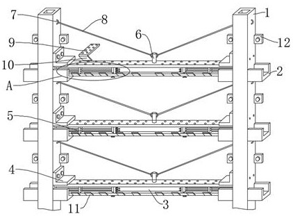
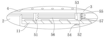
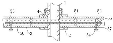
[0016] see Figure 1-4 , the present invention provides a technical solution: a load-bearing frame of a high-rise building outer steel structure, including a plurality of main steel columns 1, the two sides of the main steel columns 1 are fixed with welded connection blocks 12, and the connection blocks 12 are connected to the outer wall of the building through expansion bolts , the outer walls on both sides of the main steel column 1 are also fixed with welde...


PUM


Abstract

The invention discloses a load-bearing frame of an outer steel structure of a high-rise building. The two ends of the I-beam are clamped in the card seat between the adjacent main steel columns. The cover plate is installed on the outer wall of the main steel column on the top of the card seat through bolts. The cover plate is pressed tightly on the I-beam. The I-beams on both sides of the main steel column A prestressing mechanism is installed between the beams, and a suspender is installed in the middle of the I-beam, and the suspender is connected to the main steel column through a steel wire rope, and a bearing plate is installed on the I-beam through bolts. The I-beam is clamped by the card seat and fixed by the cover plate. Then the I-beam and the main steel column are located on the same plane, reducing the overall thickness of the frame and increasing the stability. The upward prestress is applied to the middle of the I-beam through the prestressing mechanism. At the same time, the middle part of the I-beam is hoisted by the steel wire rope to reduce the bending stress on the middle part of the I-beam when carrying objects, so that the bearing capacity of the load-bearing frame is improved.

Description

technical field [0001] The invention relates to the technical field of building exterior walls, in particular to a load-bearing frame of a high-rise building exterior steel structure. Background technique [0002] The outer walls of high-rise buildings are often provided with some steel structure frames for installing some outer wall decorations. Most of the current steel structure load-bearing frames include vertical columns fixed on the building exterior walls and load-bearing beams installed on the columns by bolts. Easy to install, the load-bearing beam is installed on the side of the column away from the wall, but if the overall thickness of the frame increases, the shear stress moment on the connection between the column and the wall will increase, which will reduce the overall bearing capacity of the frame, and The middle part of the load-bearing beam will be bent downward due to the gravity of the load-bearing object. In order to increase the stability of the load-be...

Claims


Application Information

Patent Timeline
Patent Type & Authority Patents(China)
IPC IPC(8): E04F13/21E04F13/22
CPCE04F13/0803
Inventor 张旭东
Owner 中旭水务环保科技有限公司
Why Eureka
Try Eureka