
A water-air separation device for concentrated feed processing

A water-gas separation and concentrated feed technology, which is applied to heating devices, drying solid materials, lighting and heating equipment, etc., can solve the problems of poor drying efficiency, water can not be used for secondary heat conduction, etc., so as to avoid waste and realize water Gas separation, to achieve the effect of uniform distribution

Active Publication Date: 2020-07-24
徐州德诚饲料有限责任公司
View PDF6 Cites 1 Cited by
  • Summary
  • Abstract
  • Description
  • Claims
  • Application Information

AI Technical Summary

Problems solved by technology

[0008] The invention proposes a water-air separation device for concentrated feed processing, which solves the problems that the water generated in the water-air separation process cannot be reused and the heat conduction effect is poor in the process, resulting in poor drying efficiency.

Method used


Image

  • A water-air separation device for concentrated feed processing
  • A water-air separation device for concentrated feed processing
  • A water-air separation device for concentrated feed processing

Examples


Embodiment 1

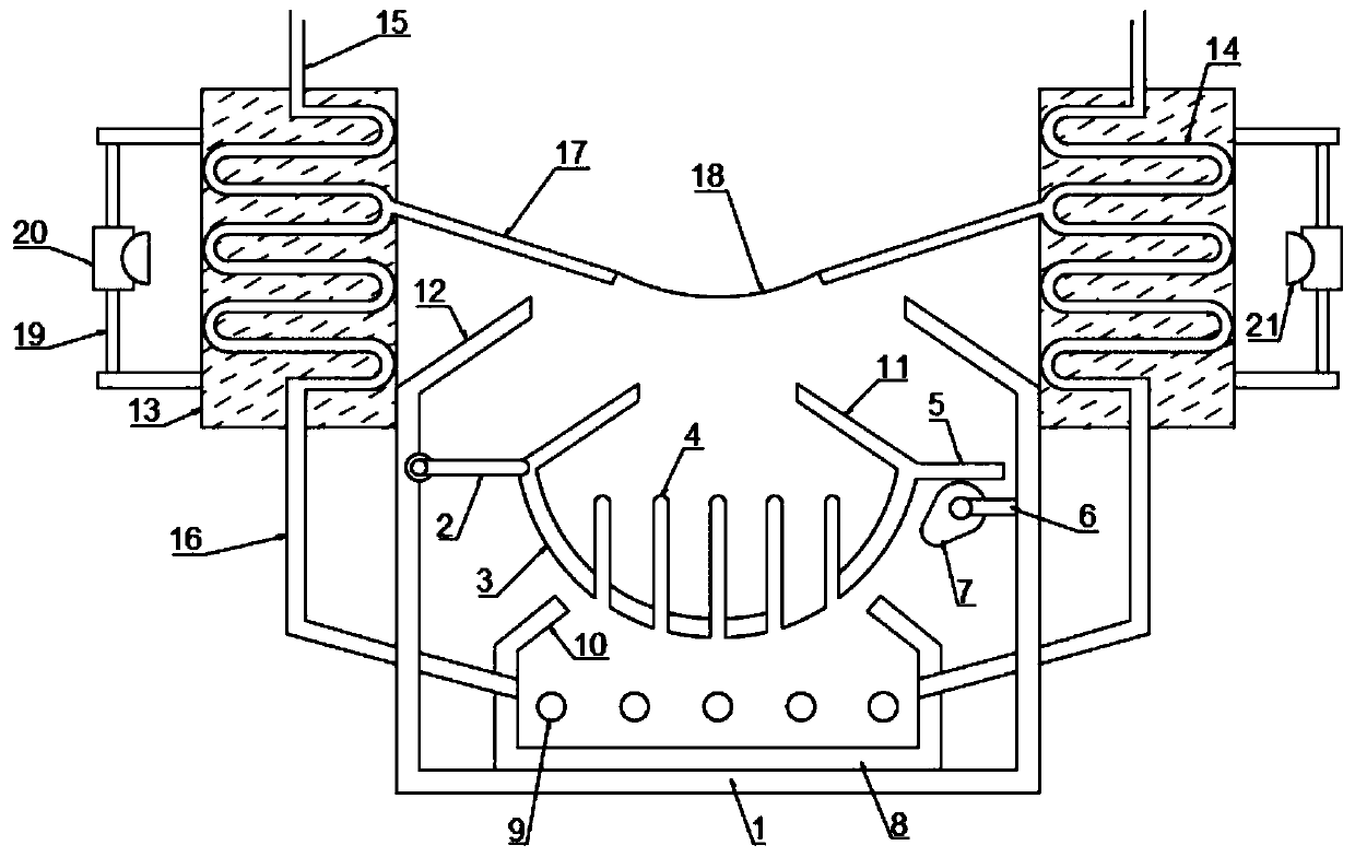
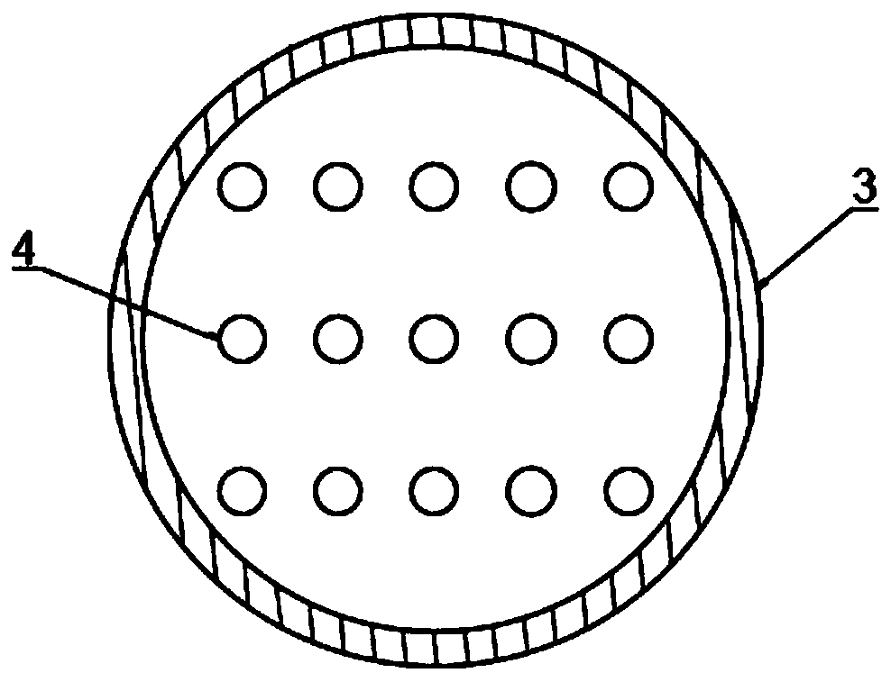
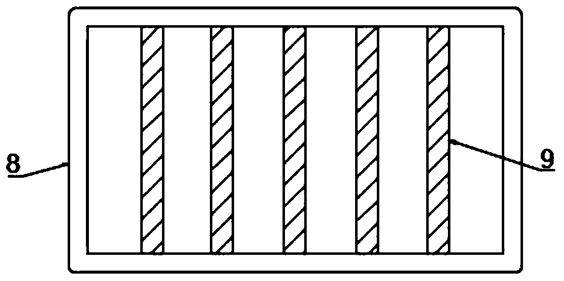
[0029] refer to Figure 1-3 , a water-air separation device for concentrated feed processing, comprising a box body 1, a rotating rod 2 is rotatably connected to one side of the inner wall of the box body 1, and the other end of the rotating rod 2 is fixed with a swing groove 3, and the inner bottom wall of the swing groove 3 An air intake pipe 4 arranged vertically downward is integrally formed, and a wobble plate 5 arranged symmetrically with the rotating rod 2 is fixed on the outer wall of the oscillating groove 3, and a wobble plate 5 is arranged between the lower side wall of the wobble plate 5 and the inner wall of the box body 1. mechanism, the swing mechanism includes a fixed rod 6 fixed on the inner wall of the box body 1, a motor one is fixed on the end of the fixed rod 6 far away from the inner wall of the box body 1, and a cam 7 is fixed on the driving end of the motor one, and the motor one drives the cam 7 to rotate. When the longer end of the cam 7 is turned to ...

Embodiment 2

[0036] refer to Figure 2-4, a water-air separation device for concentrated feed processing, comprising a box body 1, a rotating rod 2 is rotatably connected to one side of the inner wall of the box body 1, and the other end of the rotating rod 2 is fixed with a swing groove 3, and the inner bottom wall of the swing groove 3 An air intake pipe 4 arranged vertically downward is integrally formed, and a wobble plate 5 arranged symmetrically with the rotating rod 2 is fixed on the outer wall of the oscillating groove 3, and a wobble plate 5 is arranged between the lower side wall of the wobble plate 5 and the inner wall of the box body 1. mechanism, the swing mechanism includes a limit plate 22 fixed on the inner wall of the box body 1, a rack 23 is inserted on the limit plate 22, a motor 2 is fixed inside the box body 1, and the driving end of the motor 2 is fixed on the rack 23 The incomplete gear 24 on one side, when the motor 2 drives the incomplete gear 24 to mesh with the r...


PUM


Abstract

The invention belongs to the technical field of feed processing, and particularly relates to a water-air separation device for concentrated feed processing. In order to solve the problems that water generated in the water-air separation process of existing feed cannot be subjected to secondary utilization, and the heat conduction effect in the water-air separation process is poor, so that the drying efficiency is poor, the following scheme is provided, specifically, the water-air separation device comprises a box body, the inner wall of one side of the box body is rotationally connected with one end of a rotary rod, and the other end of the rotary rod is fixedly provided with a swing groove; and air intake pipes vertically arranged downwards are integrally formed on the inner bottom wall of the swing groove, a swing plate symmetrical with the rotary rod is fixed to the outer wall of the swing groove, and a swing mechanism is arranged between the lower side wall of the swing plate and the inner wall of the box body. According to the water-air separation device, the swing groove is heated through water vapor, uniform distribution of heat is achieved through swing of the swing groove,the drying effect is ensured, the water vapor generated in the drying process enters a cooling pipe to be converted into condensate water for secondary utilization, dried air is guided out, and water-air separation is achieved.

Description

technical field [0001] The invention relates to the technical field of feed processing, in particular to a water-gas separation device for concentrated feed processing. Background technique [0002] Concentrated feed, also known as protein supplement feed, is a compound feed semi-finished product prepared from protein feed (fish meal, bean cake, etc.), mineral feed and additive premix. Then mixed with a certain proportion of energy feed, it becomes a full-price feed that meets the nutritional needs of animals. It has the advantages of high protein content, comprehensive nutritional components, and convenient use. [0003] Concentrated feed contains a large number of beneficial microorganisms, effectively removes anti-nutritional factors and toxic and harmful substances in raw materials, and significantly improves the quality of raw materials; it can degrade macromolecular proteins, cellulose, hemicellulose, etc. into small peptides, amino acids, oligosaccharides, Monosaccha...

Claims


Application Information

Patent Timeline
Patent Type & Authority Patents(China)
IPC IPC(8): F26B17/26F26B23/10F26B25/00F26B25/04
CPCF26B17/263F26B23/10F26B25/00F26B25/04
Inventor 魏明星
Owner 徐州德诚饲料有限责任公司
Learn More