Sand filling method compaction detection system and detection method

A detection system and detection method technology, applied in the direction of measuring devices, specific gravity measurement, instruments, etc., can solve the problems of long time spent on manual digging, high compactness of roadbed soil layer, sedimentation, etc., and achieve the effect of improving excavation efficiency

Active Publication Date: 2019-10-18
深圳市实瑞建筑技术有限公司
View PDF14 Cites 3 Cited by
  • Summary
  • Abstract
  • Description
  • Claims
  • Application Information

AI Technical Summary

Problems solved by technology

This is very detrimental to the control of the quality of earthwork filling. Due to insufficient detection, the unqualified filling and compaction projects will pass the acceptance inspection, which will lead to a series of problems such as sedimentation and cracking during the operation of the project, which will seriously shorten the actual service life of the project. , causing adverse social impact
And as my country's engineering construction attaches great importance to quality issues and requires the standardization of construction processes, the backward on-site manual inspection methods at this stage are far from meeting the needs
[0004] Among them, manual digging takes the longest time, because the compactness of the subgrade soil layer after being compacted is relatively high, time-consuming and labor-intensive when digging holes, and the efficiency is very low

Method used


Image

  • Sand filling method compaction detection system and detection method
  • Sand filling method compaction detection system and detection method
  • Sand filling method compaction detection system and detection method

Examples


Embodiment 2

[0057] A method for detecting the degree of compaction by sand filling method, comprising the following steps:

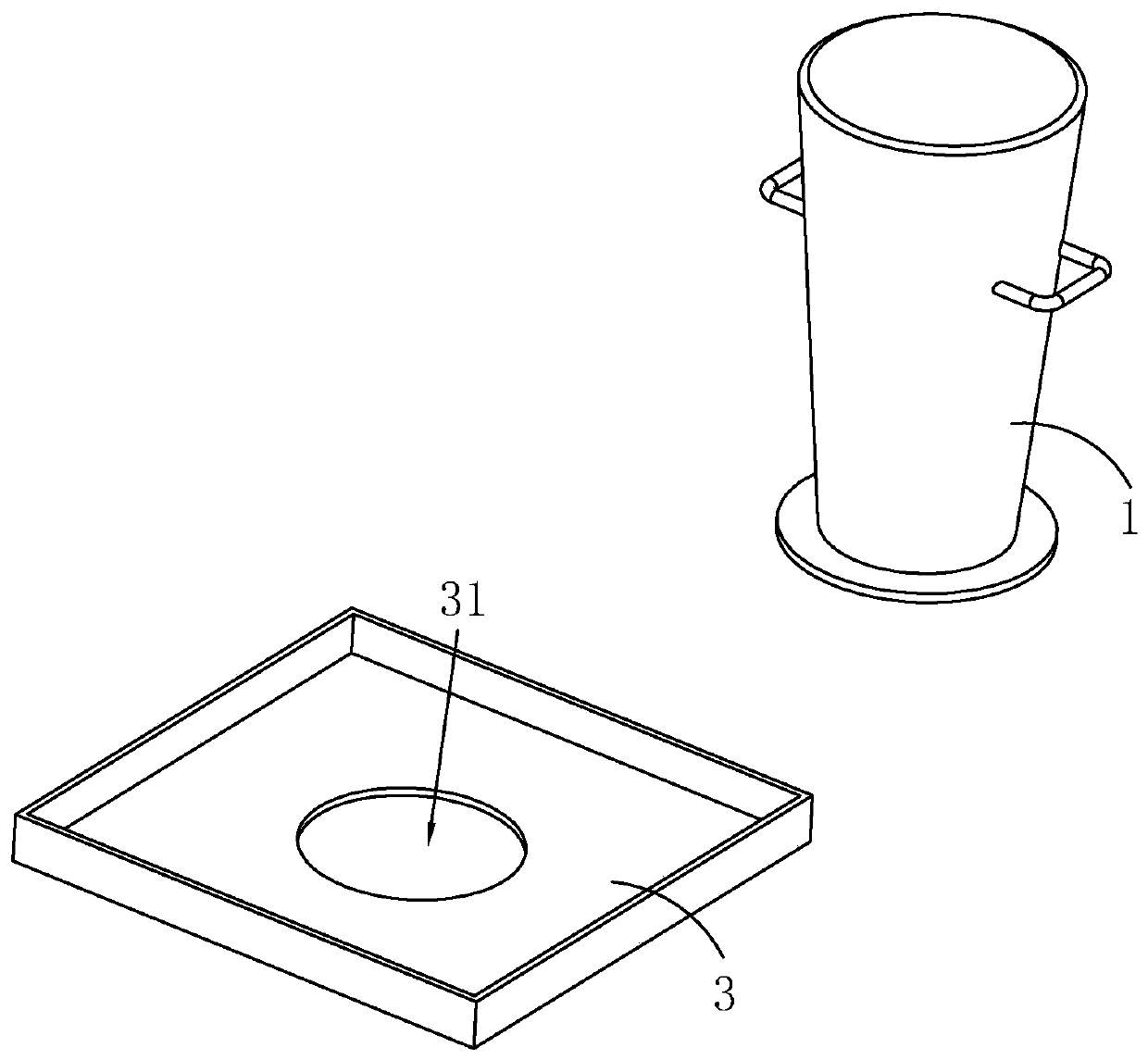
[0058] S1, select the sampling site, and mark it with a line, and place the soil collection box 3 at the mark;

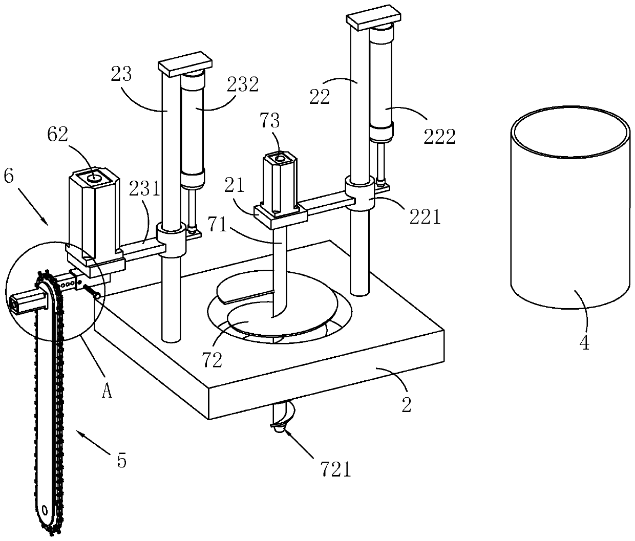
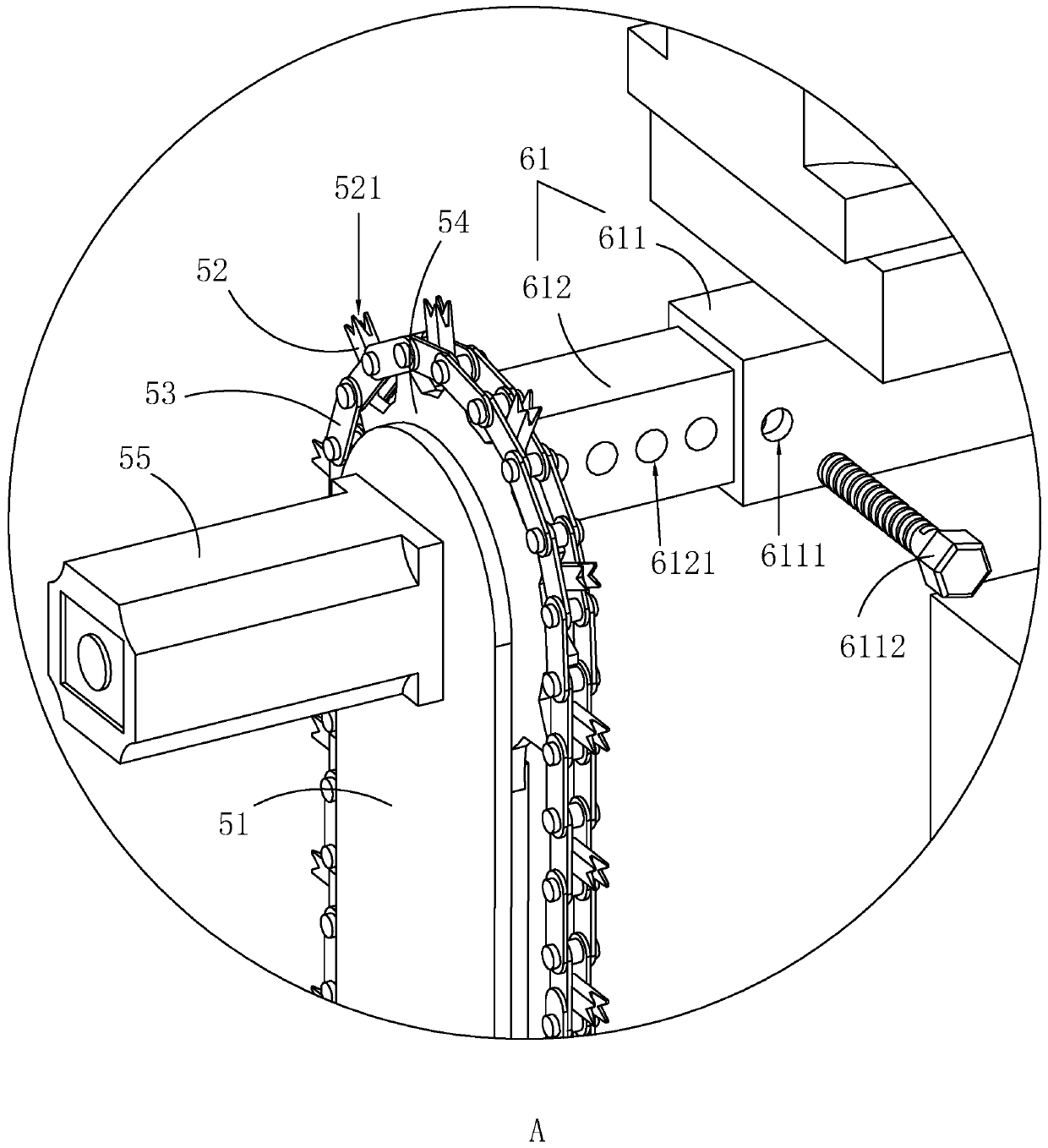
[0059] S2, drive the cutting assembly 5 to move around the round hole 31 of the soil collection box 3 through the driving assembly 6, so that the cutting assembly 5 cuts a cylindrical cutting seam on the foundation, and the depth of the cutting seam reaches the bottom of each compacted layer;

[0060] S3. Insert the casing 4 into the cutting seam. When the insertion is difficult, tap the top wall of the casing 4 with a hammer until the insertion depth of the casing 4 is equal to the depth of the cutting seam;

[0061] S4, excavating a hole and taking soil, digging out the soil in the casing 4 into the soil collecting box 3 through the excavating component to form a cylindrical foundation hole;

[0062] S5. Take out the casing 4, clean the soil at the bot...


PUM


Abstract

The invention relates to a sand filling method compaction detection system, and belongs to the technical field of road compaction detection. The sand filling method compaction detection system comprises a sand filling cylinder, a pedestal, a soil collection box and a protection cylinder with two opening ends; a round hole is formed in the middle of the soil collection box; the pedestal is providedwith a cutting component used for cutting the ground, and a driving component used for driving the cutting component to make circular motion is arranged on the pedestal; a moving base is arranged onthe pedestal along a vertical direction in a sliding manner, and a driving source is arranged on the pedestal; and a soil excavation component used for hole digging is arranged on the moving base. A cylindrical cutting slot is cut in the foundation via the cutting component; and then the protection cylinder is pressed into the cutting slot, and the pedestal position is moved, so that the soil excavation component right faces the protection cylinder, and then excavates soil in the protection cylinder out via the soil excavation component. The soil excavation efficiency is effectively improved,meanwhile, the soil around the cutting slot is separated via the protection cylinder, the soil around the soil excavation component is prevented from being excavated to cause excessive excavation, andthe measurement accuracy is improved.

Description

technical field [0001] The invention relates to the technical field of road compaction detection, in particular to a system and a detection method for the detection of compaction by sand filling method. Background technique [0002] The filling and compaction of the base course and surface course of roads, railways and airports all need to be tested for the degree of compaction. Among the existing testing methods, the sand filling method is the most widely used. Based on the strict control of the quality of compaction to ensure the quality of the project, the current code has higher requirements for the frequency of compaction testing. [0003] In engineering practice, compaction testing is often a labor-intensive project for testing personnel. During the peak season of subgrade construction, a large number of testing personnel are required to be stationed on site for testing. On-site manual digging, sand filling, sand recovery, and burning of moisture content, etc. A serie...

Claims


Application Information

Patent Timeline
Patent Type & Authority Applications(China)
IPC IPC(8): G01N9/36G01N9/02
CPCG01N9/02G01N9/36
Inventor 白智慧毛宇孙元静周少敬许铖罗发明
Owner 深圳市实瑞建筑技术有限公司
Why Eureka
Try Eureka