A Method of Determining Turning Spill at Intersection Using Single Vehicle Trajectory

An intersection and trajectory technology, which is applied to the traffic control system of road vehicles, control traffic signals, and traffic flow detection, etc., to achieve the effect of less data demand and real-time estimation

Active Publication Date: 2020-12-11
ZHEJIANG UNIV
View PDF6 Cites 0 Cited by
  • Summary
  • Abstract
  • Description
  • Claims
  • Application Information

AI Technical Summary

Problems solved by technology

Steer overflow is difficult to detect with coil detectors usually laid below the road surface

Method used


Image

  • A Method of Determining Turning Spill at Intersection Using Single Vehicle Trajectory
  • A Method of Determining Turning Spill at Intersection Using Single Vehicle Trajectory
  • A Method of Determining Turning Spill at Intersection Using Single Vehicle Trajectory

Examples


Embodiment Construction

[0031] The present invention will be described in further detail below in conjunction with the accompanying drawings.

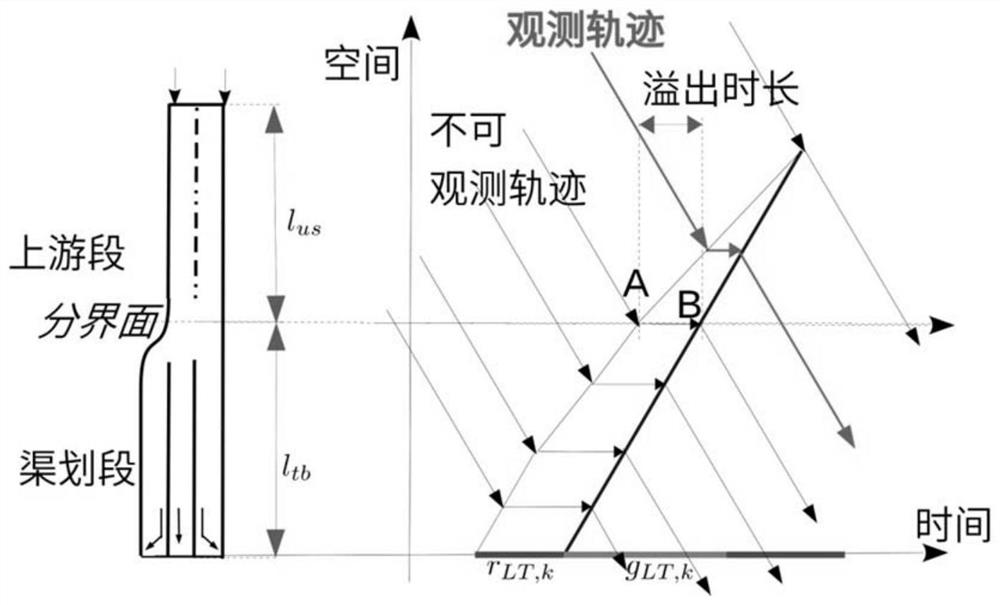
[0032] figure 1 Shown is a typical turn overflow scenario where a left turn overflow occurs and the left turn queuing spreads to the upstream segment. Straight traffic is blocked by left turn overflow. Negative effects of turn overflow include: (1) intersection capacity is consumed; (2) delays for blocked traffic flow increase; (3) travel times for entire road segments become unreliable.

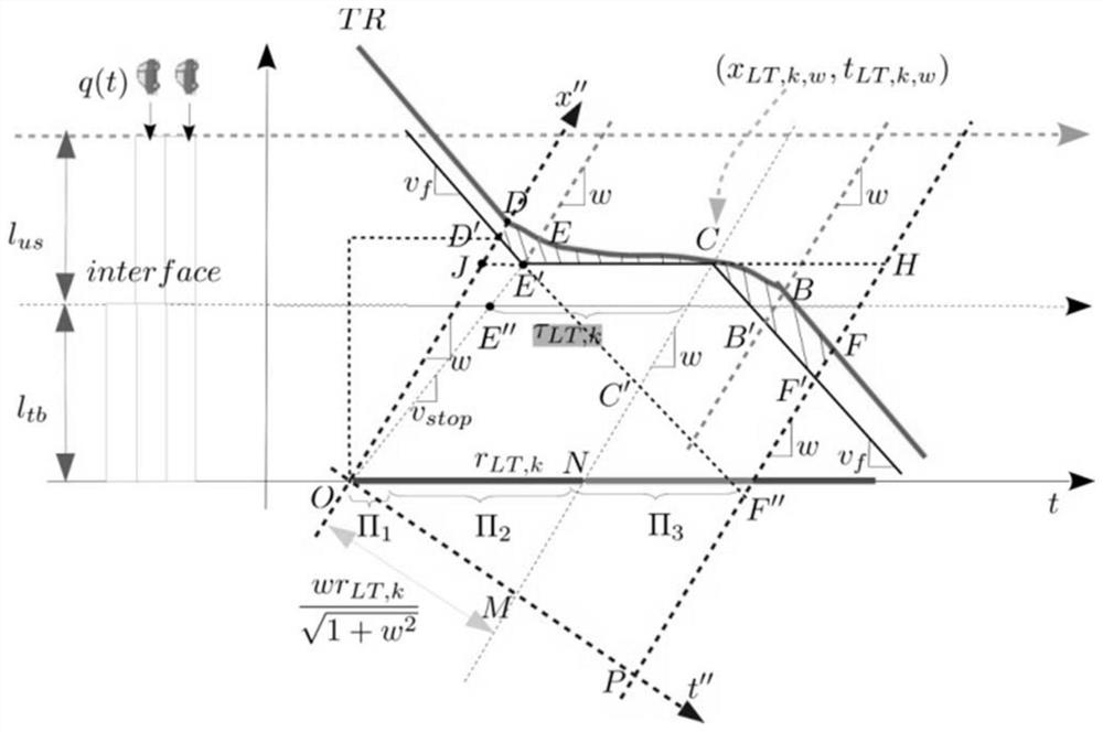
[0033] Steer overflow can occur in both left turns and through traffic. Each steering overflow event can be expressed by two parameters: start time and end time. The difference between the end time and the start time is the overflow duration. figure 2 Shown is the link topology and description of overflow events. Among them, the schematic diagram assumes left-turn overflow. In the kth period, the time for turning left at the red light is r LT,k , the green light dur...


PUM


Abstract

The invention discloses a method for determining intersection steering overflow by bicycle track. The method comprises the steps of firstly, determining topological information and signal parameter state information of an intersection inlet lane, and acquiring time-space moving track, namely actual track, of a single vehicle in the intersection inlet lane; and secondly, determining expected trackof the vehicle under the condition of steering overflow by a time-space track diagram of the vehicle with regard to arbitrary possible steering overflow frame, and determining steering overflow lengthand triggering overflow steering according to the difference between the expected track and the actual track. By the method, whether overflow exists or not can be determined only by combining a signal state and by the track of the single vehicle, and the special steering traffic flow of overflow is triggered.

Description

technical field [0001] The invention relates to a method for determining the presence or absence of steering overflow at an intersection, the specific steering and overflow duration that trigger the overflow, under the condition that the space-time trajectory of a single vehicle is known. Background technique [0002] Turning overflow at an intersection refers to the phenomenon that the channel planning area at the intersection cannot accommodate an excessively long vehicle queue, causing the vehicle queue to spread upstream and block other turning traffic flows. Due to the limitation of road land, the road sections of urban arterial roads are generally planned near the intersection, that is, the lanes are divided according to the steering. This section is called "canal planning section", vehicles are not allowed to change lanes, and the upstream lane without turning is called "upstream section". During the traffic peak period, due to the excessive arrival of traffic, the q...

Claims


Application Information

Patent Timeline
Patent Type & Authority Patents(China)
IPC IPC(8): G08G1/01G08G1/07G08G1/123
CPCG08G1/0104G08G1/07G08G1/123
Inventor 祁宏生戴茹梦
Owner ZHEJIANG UNIV
Why Eureka
Try Eureka