Multifunctional key chain

A key chain and multi-functional technology, applied in the field of key chains, can solve the problem that it cannot be used as a mobile phone holder, and achieve the effect of improving functionality

Pending Publication Date: 2019-10-22
范玉秋
0 Cites 3 Cited by

AI-Extracted Technical Summary

Problems solved by technology

[0003] In order to make up for the above deficiencies, the object of the present invention is to provide a multifunctional key chain, which aims to imp...

Method used

Concrete, described hanging plate 501 is provided with zigzag anti-slip stripe 503 near the side of groove position 101, and under hanging object state, base 1 is vertical, first upper cover 3 is launched, then hanging p...

Abstract

The invention relates to the technical field of key chain, specifically is a multifunctional key chain, which comprises a base; a cavity, the opening of which is arranged upwards, is opened on the topof the base; one side in the cavity is movably connected with an upper cover by a first flower shaft; the other side in the cavity is movably connected with a hanging disk by a second flower shaft; aconnection ring is arranged at the end of the base near one side of the first flower shaft; a hanging ring is arranged on the connection ring; a slot position is arranged on the base; the upper covercan be folded in the slot position; and, the hanging disk comprises a strip-shaped plate body. When the upper cover and the hanging disk are contained, the device can be directly used as the key chain; when the key chain is in the hanging state, the base is placed vertically and the plate body is unfolded; at this time, an object can be hanged on the hanging disk; when the key chain is used as adesk mobile phone holder, the base is placed horizontally; at this time, the mobile phone is leaned against the upper cover; the bottom end of the mobile phone is leaned in the slot position; and thus, the functionality of the device is improved.

Application Domain

Key-rings

Technology Topic

Multiple functionElectrical and Electronics engineering +1

Image

  • Multifunctional key chain
  • Multifunctional key chain
  • Multifunctional key chain

Examples

  • Experimental program(1)

Example Embodiment

[0019] The technical solutions in the embodiments of the present invention will be clearly and completely described below with reference to the accompanying drawings in the embodiments of the present invention. Obviously, the described embodiments are only a part of the embodiments of the present invention, but not all of the embodiments. Based on the embodiments of the present invention, all other embodiments obtained by those of ordinary skill in the art without creative efforts shall fall within the protection scope of the present invention.
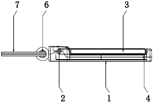
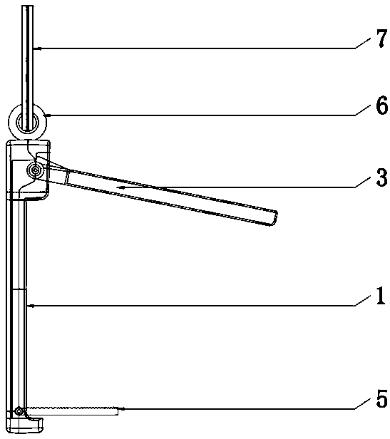
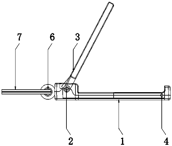
[0020] see Figure 1-6 , the present invention provides a technical solution: a multifunctional keychain, comprising a base 1, the top of the base 1 is provided with a cavity with an upward opening, and one side of the cavity is movably connected with a first spline 2. The upper cover 3, the other side of the cavity is movably connected with a hanging plate 5 through the second spline 4, and the end of the base 1 close to the first spline 2 is provided with a connecting ring 6, and the connecting ring 6 is provided with There is a hanging ring 7, the connecting ring 6 is used to connect the hanging ring 7, the base 1 is provided with a slot 101, the upper cover 3 can be folded in the slot 101, and the design of the slot 101 is convenient for the upper cover 3 When unfolded, the hanging tray 5 includes a bar-shaped hanging tray 501. The hanging tray 5 can also be unfolded for use. Please refer to figure 1 , figure 1 It is a schematic diagram when both the upper cover 3 and the hanging tray 5 are in the storage state. At this time, the device can be directly used as a keychain; please refer to figure 2 , figure 2 It is a schematic diagram of the structure in the state of hanging objects; please refer to image 3 , image 3 As a schematic diagram of the structure in the state of the desktop mobile phone bracket, the mobile phone is leaning on the upper cover 3 at this time, and the bottom end of the mobile phone is abutting in the slot 101, which improves the functionality of the device.
[0021] Specifically, the upper cover 3 includes a bar-shaped cover body 301 . One end of the cover body 301 is provided with a first shaft hole 302 corresponding to the first spline 2 , and the cover body 301 can wrap around the first spline 2 . Open.
[0022] Specifically, one end of the hanging tray 501 is provided with a second shaft hole 502 corresponding to the second spline 4 , and the hanging tray 501 can be opened around the second sprocket 4 .
[0023] Specifically, the side of the hanging tray 501 close to the slot 101 is provided with serrated anti-slip stripes 503. In the hanging object state, the base 1 is upright, and the upper cover 3 is first unfolded, and then the hanging tray 501 is unfolded. Objects can be hung on the hanging tray 501. Since the side of the hanging tray 501 close to the slot 101 is provided with serrated anti-slip stripes 503, it has a good anti-slip effect.
[0024] Specifically, the opening angle of the upper cover and the base ranges from 50 degrees to 90 degrees, and the opening angle of the hanging tray and the base ranges from 75 degrees to 90 degrees.
[0025] Specifically, the cover body 301 can be deflected around the first spline 2 , the design of the slot 101 facilitates the unfolding of the upper cover 3 , and the hanging tray 501 can be deflected around the second spline 4 , figure 1 It is a schematic diagram when both the upper cover 3 and the hanging tray 5 are in the storage state. At this time, the device can be directly used as a keychain. In the hanging object state, the base 1 is vertical, and the upper cover 3 is unfolded first, and then the hanging tray 501 When unfolded, objects can be hung on the hanging tray 501. When used as a desktop mobile phone bracket, the base 1 is placed horizontally. At this time, the mobile phone is against the upper cover 3, and the bottom end of the mobile phone is against the slot 101, which improves the device The functionality is suitable for promotion.
[0026] The foregoing has shown and described the basic principles, main features, and advantages of the present invention. Those skilled in the art should understand that the present invention is not limited by the above-mentioned embodiments, and the descriptions in the above-mentioned embodiments and the description are only to illustrate the principle of the present invention. Without departing from the spirit and scope of the present invention, the present invention will have Various changes and modifications fall within the scope of the claimed invention. The claimed scope of the present invention is defined by the appended claims and their equivalents.

PUM

no PUM

Description & Claims & Application Information

We can also present the details of the Description, Claims and Application information to help users get a comprehensive understanding of the technical details of the patent, such as background art, summary of invention, brief description of drawings, description of embodiments, and other original content. On the other hand, users can also determine the specific scope of protection of the technology through the list of claims; as well as understand the changes in the life cycle of the technology with the presentation of the patent timeline. Login to view more.

Similar technology patents

Multipoint data transmission method

ActiveCN104168319AImprove functionalityOptimize topology
Owner:耘申信息科技(上海)有限公司

Production method of anti-ultraviolet fiber

ActiveCN103469329AImprove functionality
Owner:广东省化学纤维研究所有限公司

Waterproof touch glove for capacitive screen

Owner:WEIHAI YUNRUI INFORMATION TECH CO LTD

Control system for manual transmissions

InactiveUS20170089413A1reduces cost and complexityimprove functionality
Owner:BORG WARNER INC

Classification and recommendation of technical efficacy words

Why Eureka
Try Eureka