Mobile ICU system

A technology of linkage mechanism and bed body, applied in the medical field, can solve the problems of inability to meet the needs of patients, single structure and function of the bed in the ward, etc., and achieve the effect of improving market competitiveness, improving comfort, and facilitating movement and use.

Inactive Publication Date: 2019-10-22
南京市江宁医院
View PDF6 Cites 1 Cited by
  • Summary
  • Abstract
  • Description
  • Claims
  • Application Information

AI Technical Summary

Problems solved by technology

[0003] The purpose of the present invention is to provide a mobile ICU system to solve the problem that the structure and function of the bed in the ward proposed in the above-mentioned background technology cannot meet the needs of patients

Method used


Image

  • Mobile ICU system
  • Mobile ICU system
  • Mobile ICU system

Examples


Embodiment 1

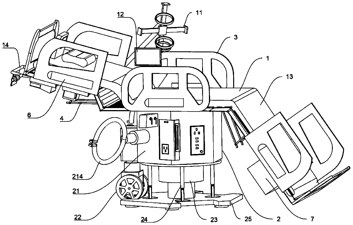
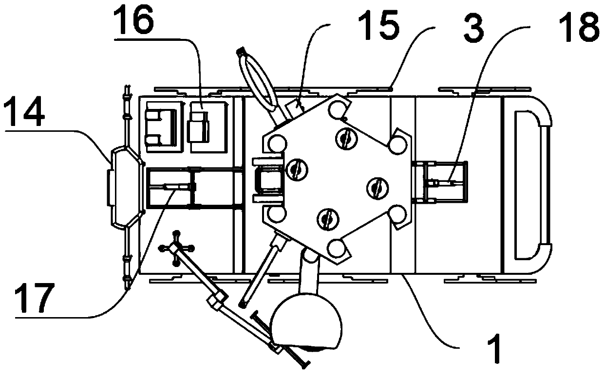
[0042] A mobile ICU system, such as Figure 1-5 As shown, it includes a bed body 1, armrests 3 symmetrically arranged on both sides of the bed body 1, and a main base 2 installed at the bottom of the bed body 1. The main base 2 includes a control box 21, and a main push rod 23 is installed at the bottom of the control box 21 A number of load-bearing universal wheels 24 are installed at equal intervals around the main push rod 23. The bottom of the main push rod 23 is provided with a load-bearing bottom plate 25. A micro ventilator 16 is installed near the head of the bed body 1. An instrument flap 161 is installed, and a defibrillator 15 is installed on the right side of the main base 2 for easy access to the electrode plate.

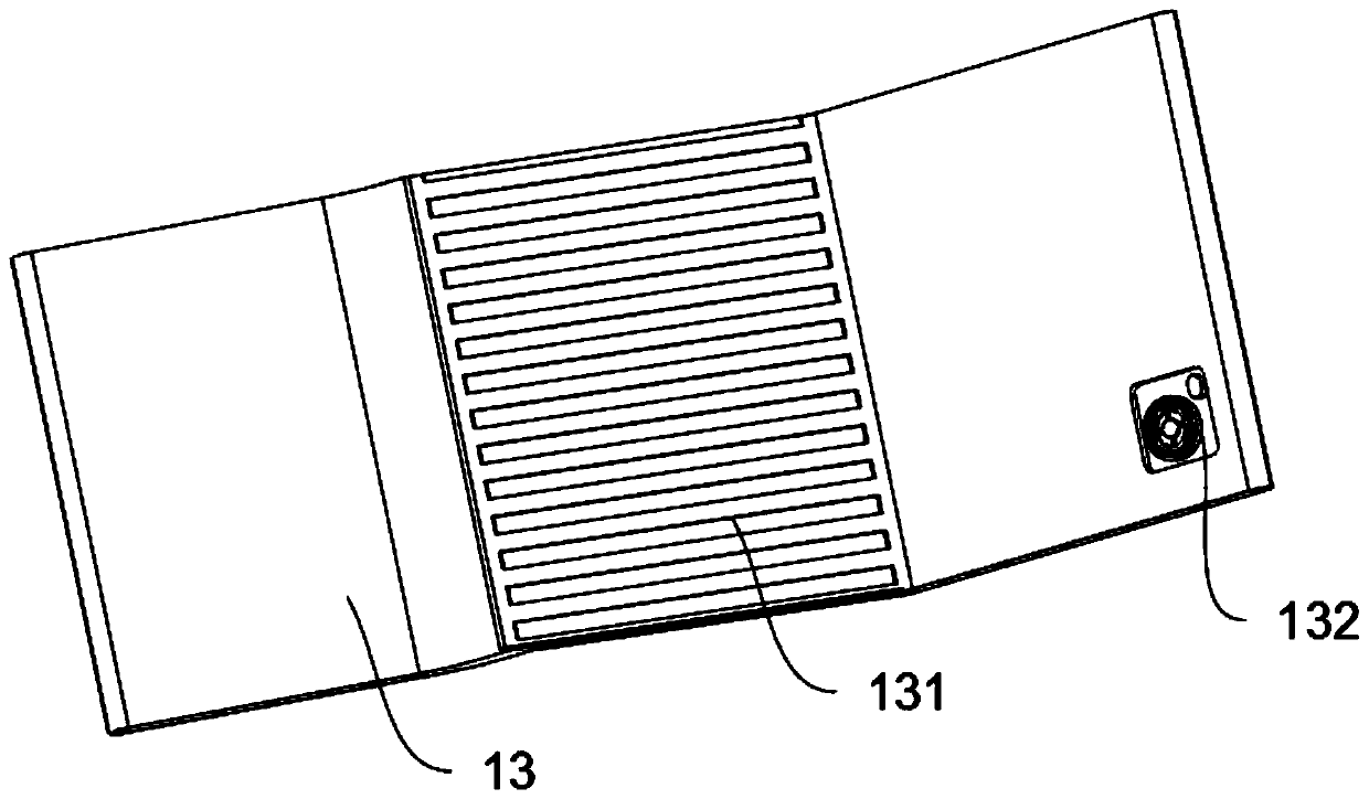
[0043] In this embodiment, the upper surface of the bed 1 is provided with a hot and cold double-effect mattress 13, and the center of the lower surface of the hot and cold double-effect mattress 13 is provided with a thermal resistance sheet 131. When the ...

Embodiment 2

[0049] As a second embodiment of the present invention, in order to facilitate fixing the oxygen cylinder and collecting garbage, the personnel of the present invention set up a negative pressure suction device 213 and an oxygen cylinder fixing frame 214, as a preferred embodiment, such as Figure 6-9 As shown, the main motor 22 is installed on the left side of the control box 21, and two symmetrical oxygen cylinder holders 214 are installed on the side wall of the control box 21. One side of the oxygen bottle holder 214 is provided with a battery 211. The side wall of 211 is equipped with a plug-in board 212, the other oxygen cylinder holder 214 is equipped with a negative pressure suction device 213, and one side of the negative pressure suction device 213 is equipped with a control panel 215, a negative pressure suction device 213 A motor push rod 216 is provided at the bottom of the motor push rod 216, and a rotating base 2161 is provided at the bottom of the motor push rod 2...

Embodiment 3

[0057] As the third embodiment of the present invention, in order to facilitate the adjustment of the height of the head and foot of the bed 1 and improve the practicability, the present inventors set up a linkage mechanism 4 as a preferred embodiment, such as Picture 10 As shown, the lower surface of the bed body 1 is equipped with a linkage mechanism 4 near the two ends. The linkage mechanism 4 includes a fixed link 45. The two ends of the fixed link 45 are provided with a master-slave linkage rod 42. The two ends of the moving rod 42 are respectively hinged with an active rod 41 and an auxiliary linkage rod 43, and both ends of the active rod 41 are respectively provided with a linkage rod 44 and a connecting rod 46.

[0058] In this embodiment, between the fixed connecting rods 45 and the connecting rods 46 of the two linkage mechanisms 4, there are installed a bedside motor push rod 17 and a bed end motor push rod 18, and the bottom of the bed head motor push rod 17 and the b...


PUM


Abstract

The invention relates to the technical field of medical technology, in particular to a mobile ICU system. The system comprises a bed body, armrests symmetrically arranged on two sides of the bed bodyand a main base mounted on the bottom of the bed body. The main base comprises a control cabinet, the bottom of which is provided with a main push rod. Several load-bearing universal wheels are installed at equal intervals around the main push rod, the bottom of which is equipped with a load-bearing bottom plate. Through the designed hot and cold double-effect mattress, the temperature of the surface of the bed body can be adjusted to prevent too low or too high temperature from causing discomfort of a patient, thus improving comfort of the patient. Through a designed linkage mechanism, the height of the head and end of the bed body can be adjusted such that the patient can be in semireclining position; the head of the bed also can be fully raised and the end of the bed can be completely lowered such that the system is changed into a wheelchair, which is convenient to move and use.

Description

Technical field [0001] The invention relates to the field of medical technology, in particular to a mobile ICU system. Background technique [0002] ICU is the intensive care unit for intensive care. Intensive medical care is a form of medical organization and management that integrates modern medical care technology with the development of medical care, the birth of new medical equipment and the improvement of hospital management system. ICU concentrates critically ill patients. It is necessary to provide the best guarantee in terms of manpower, material resources and technology in order to obtain a good treatment effect. The bed in the ward is particularly important for the patient. The structure and function of the bed in the ward are currently single and cannot meet the needs of the patients. In view of this, we propose A mobile ICU system. Summary of the invention [0003] The purpose of the present invention is to provide a mobile ICU system to solve the problem that the st...

Claims


Application Information

Patent Timeline
Patent Type & Authority Applications(China)
IPC IPC(8): A61G7/015A61G7/05A61G7/075A61B5/024
CPCA61B5/0245A61G7/015A61G7/018A61G7/05A61G7/075A61G2203/20A61G2210/30A61G2210/90
Inventor 张祥
Owner 南京市江宁医院
Why Eureka
Try Eureka