Ceramic disc lifting mechanism

A technology of ceramic disc and fixed structure, applied in the direction of lifting device, lifting frame, etc., can solve the problems of inconvenient transportation and technological processing, and achieve the effect of convenient transportation and processing, and meet various needs.

Inactive Publication Date: 2019-10-22
SHANGHAI TUNA ELECTRIC MECHANIC EQUIP CO LTD
View PDF7 Cites 0 Cited by
  • Summary
  • Abstract
  • Description
  • Claims
  • Application Information

AI Technical Summary

Problems solved by technology

[0004] The present invention provides a ceramic plate lifting mechanism to solve the problem that the position of the ceramic plate is fixed and it is not convenient to move to the required position for further transportation and process treatment

Method used

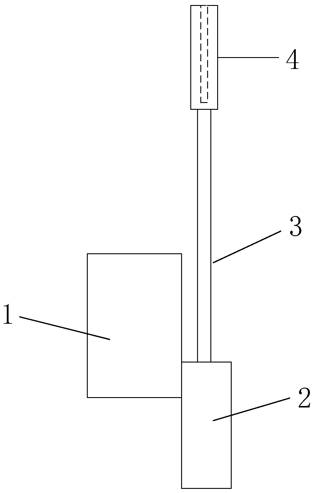
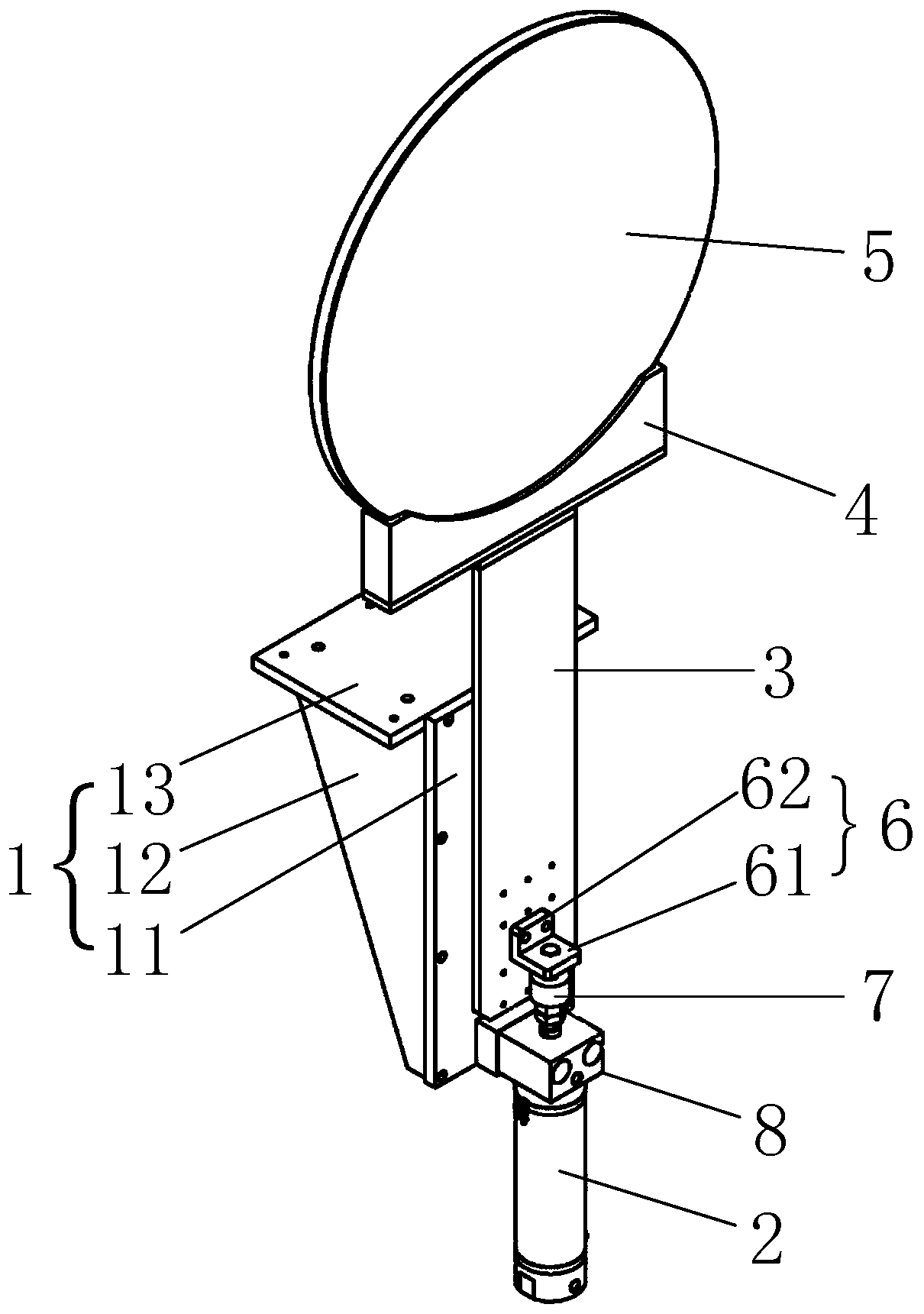
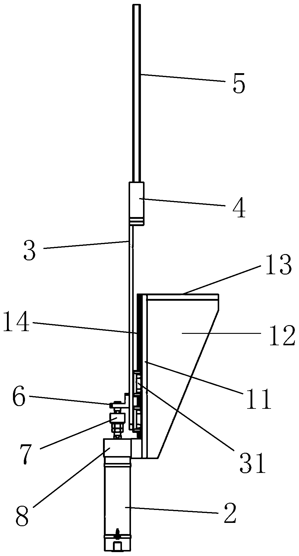

Image

  • Ceramic disc lifting mechanism
  • Ceramic disc lifting mechanism
  • Ceramic disc lifting mechanism

Examples


Embodiment Construction

[0036] The following will clearly and completely describe the technical solutions in the embodiments of the present invention with reference to the accompanying drawings in the embodiments of the present invention. Obviously, the described embodiments are only some, not all, embodiments of the present invention. Based on the embodiments of the present invention, all other embodiments obtained by persons of ordinary skill in the art without making creative efforts belong to the protection scope of the present invention.

[0037] The terms "first", "second", "third", "fourth", etc. (if any) in the description and claims of the present invention and the above drawings are used to distinguish similar objects and not necessarily Describe a specific order or sequence. It is to be understood that the data so used are interchangeable under appropriate circumstances such that the embodiments of the invention described herein can be practiced in sequences other than those illustrated or...


PUM


Abstract

The invention provides a ceramic disc lifting mechanism. The lifting mechanism comprises a clamping groove structure, a lifting plate, a fixing structure and a lifting driving structure, wherein the lifting plate is perpendicular to the ground, the clamping groove structure is connected to the upper end of the lifting plate, and the clamping groove structure is used for embedding a ceramic disc byusing the clamping groove; and the lifting driving structure is assembled on the fixing structure and used for driving the lifting plate, and the clamping groove structure at the upper end of the lifting plate and the ceramic disc are lifted together. According to the ceramic disc lifting mechanism, the ceramic disc can be lifted, so that the ceramic disc can be lifted to a required position conveniently, further transportation and processing are facilitated, and various requirements are met.

Description

technical field [0001] The invention relates to the field of ceramic discs, in particular to a ceramic disc lifting mechanism. Background technique [0002] The ceramic disk can be understood as a disc made of ceramic material, and its function can be, for example, to fix a wafer. Ceramic discs can be transported by automatic transport mechanism. [0003] In the existing related technology, the ceramic discs can be loaded on the carrier tray during storage, and the ceramic discs can also be placed on the corresponding carrier tray when the ceramic discs are placed in the corresponding stations for processing such as patching and heating. However, since the position of the ceramic discs is fixed , it is inconvenient to move to the desired location for further transportation and processing. Contents of the invention [0004] The invention provides a lifting mechanism for ceramic discs to solve the problem that the position of the ceramic disc is fixed and it is inconvenien...

Claims


Application Information

Patent Timeline
Patent Type & Authority Applications(China)
IPC IPC(8): B66F7/14B66F7/28
CPCB66F7/14B66F7/28
Inventor 韩鹏帅葛威威吴士勇葛永恒葛林四
Owner SHANGHAI TUNA ELECTRIC MECHANIC EQUIP CO LTD
Why Eureka
Try Eureka