A technology for dismantling the bearing spring of bogie

A technology for dismantling technology and bogies, which is applied in metal processing, manufacturing tools, metal processing equipment, etc., can solve the problems of potential safety hazards, high labor intensity, and low work efficiency, so as to improve disassembly efficiency, reduce labor intensity, and improve The effect of pick-and-place efficiency

Active Publication Date: 2020-05-22
成都岁生科技有限责任公司
View PDF7 Cites 0 Cited by
  • Summary
  • Abstract
  • Description
  • Claims
  • Application Information

AI Technical Summary

Problems solved by technology

[0005] The purpose of the present invention is: in order to solve the problems of high labor intensity, potential safety hazards and low work efficiency during the dismantling process of the existing bogie by manually moving the bearing spring, the present invention A bogie bearing spring removal process is provided

Method used


Image

  • A technology for dismantling the bearing spring of bogie
  • A technology for dismantling the bearing spring of bogie
  • A technology for dismantling the bearing spring of bogie

Examples


Embodiment 1

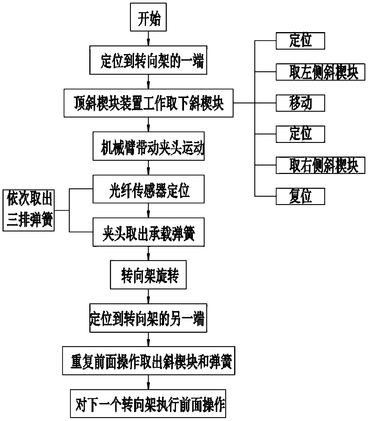
[0051] The bogie bearing spring dismounting process of the present invention comprises the following steps:

[0052] S1 is positioned to one end of the bogie 5;

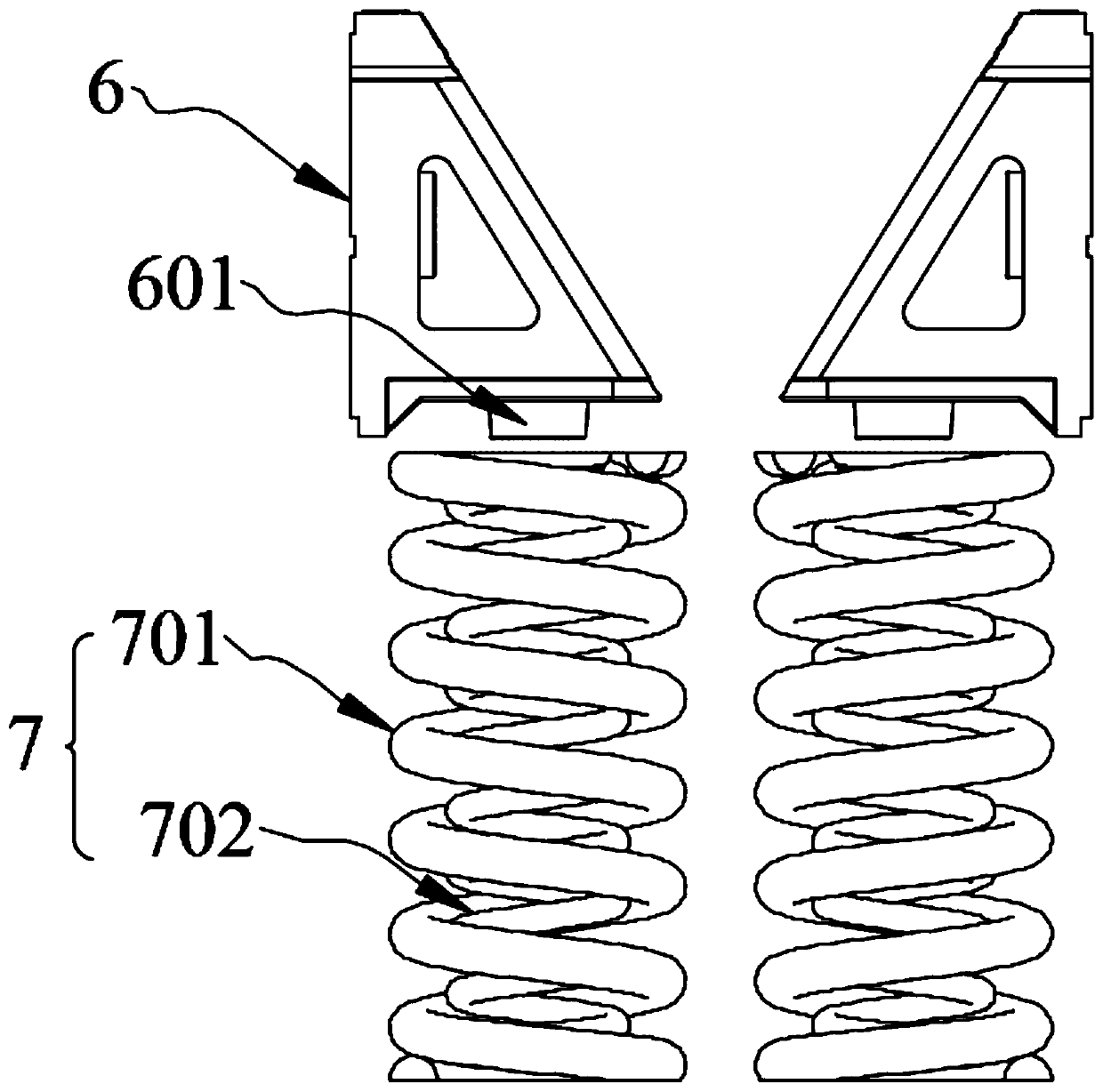
[0053] The S2 jacking device works to remove the wedge block 6;

[0054] The jacking device includes a jacking unit 4 and a three-axis cantilever. There are two jacking units 4, and the movement of the jacking unit 4 in space is realized through the three-axis cantilever, and the wedge on the left side of one of the jacking units 4 is completed. Positioning of block 6, then remove the left side wedge block 6, then move another jacking unit, 4 position the right side wedge block, 6, then remove the right side wedge block 6, and finally reset ;

[0055] S3 mechanical arm 2 drives chuck 1 to move;

[0056] The chuck 1 and the mechanical arm 2 are connected to each other through a flange 10;

[0057] S4 positioning device locates the bearing spring 7;

[0058] The through-beam optical fiber sensor 1021 positions the...

Embodiment 2

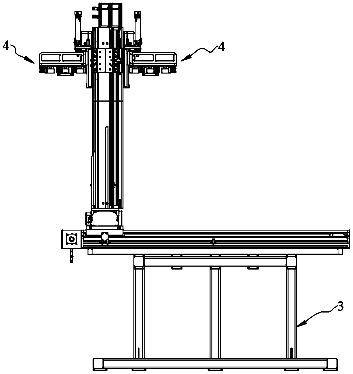
[0065] as attached Figure 3-4 As mentioned above, this embodiment is optimized as follows on the basis of Embodiment 1: the three-axis cantilever in step S2 includes X-axis guide rails 801, Y-axis guide rails 802, and Z-axis guide rails 803, all of which are equipped with ball screws. The lower end of the three-axis cantilever is provided with a bracket 3, the X-axis guide rail 801 is horizontally arranged on the upper end of the bracket 3, the Y-axis guide rail 802 is horizontally arranged on the upper end of the X-axis guide rail 801 and is perpendicular to the X-axis guide rail, and the Y-axis guide rail The lower end of the middle part of 802 is connected with the first sliding seat 8011, the first sliding seat 8011 is connected with the X-axis guide rail 801, the upper end of the Y-axis guide rail 802 is vertically connected with the Z-axis guide rail 803, and the lower end of the Z-axis guide rail 803 A second sliding seat 8021 is connected, and the second sliding seat ...

Embodiment 3

[0068] as attached Figure 5-6 As shown, this embodiment is based on Embodiment 2 and is optimized as follows: the Z-axis guide rail 803 is also connected with a third sliding seat 8031, and the jacking unit 4 is provided with two 803 is symmetrical, and the two jacking units 4 are connected to the third sliding seat 8031; the jacking unit 4 includes a laser sensor, a connecting plate 401, a jacking platform 403, a jacking rod 406 and a small cylinder 407, and the connection The plate 401 connects the jacking platform 403 and the third sliding seat 8031 ​​with each other. The upper end of the jacking platform 403 is provided with a laser sensor, and the middle part of the lower end of the jacking platform 403 is provided with a lifting plate 405. There is a U-shaped draw-in slot, and the left and right sides of the lifting plate 405 are provided with jacking rods 406, and the front end of the lifting rods 406 is located in front of the front end of the jacking platform 403, an...


PUM


Abstract

The invention discloses a bogie bearing spring disassembling process, and belongs to the technical field of disassembly of bogie bearing springs. The process is used for solving the problems that in the existing bogie disassembling process, by adopting the mode of manually carrying bearing springs, the labor intensity is large, hidden safety hazards exist in the carrying process, and the work efficiency is low. The process comprises the following steps that S1, one end of a bogie is located; S2, a jacking device works to remove tapered wedges; S3, a mechanical arm drives a chuck to move; S4, alocating device locates bearing springs, and a bijective optical fiber sensor locates outer spring bodies of the bearing springs; S5, the chuck takes out the bearing springs, and three rows of bearing springs are sequentially taken out, the out-taken bearing springs are placed on a transfer frame, and the outer spring bodies and inner spring bodies of the bearing springs are separated; S6, the bogie rotates, and the other end of the bogie is located; S7, the operation of S1 to S5 is repeated, and the tapered wedges and the bearing springs are taken out; S8, the operation of S1 to S7 is repeated for a next bogie.

Description

technical field [0001] The invention relates to the technical field of bogie dismantling, and more particularly relates to a bogie bearing spring dismantling process. Background technique [0002] The bogie is one of the most important components in the rail vehicle structure, and various parameters of the bogie also directly determine the stability of the vehicle and the ride comfort of the vehicle. During the maintenance of the bogie, the structure needs to be disassembled. The load springs are mainly removed by manual movement. The load springs at both ends of the bogie are divided into three rows: outer, middle and inner. There are differences in the number and type of load-bearing springs, and the pitch of the load-bearing springs is also different. A load-bearing spring includes an inner load-bearing spring and an outer load-bearing spring, and the inner load-bearing spring and the outer load-bearing spring are independent of each other. When carrying the spring, addi...

Claims


Application Information

Patent Timeline
Patent Type & Authority Patents(China)
IPC IPC(8): B23P19/00
CPCB23P19/00
Inventor 刘桓龙焦万均蒋越
Owner 成都岁生科技有限责任公司
Why Eureka
Try Eureka