
Probe suction device

A suction device and probe technology, applied in the direction of measuring devices, instruments, measuring electronics, etc., can solve problems such as defective products, time-consuming, small size, etc.

Inactive Publication Date: 2018-10-09
CHUNGHWA PRECISION TEST TECH
View PDF12 Cites 2 Cited by
  • Summary
  • Abstract
  • Description
  • Claims
  • Application Information

AI Technical Summary

Problems solved by technology

[0003] In the prior art, due to the small size of the micron needles of the probe card, there is no effective pick-and-place fixture for the clamping operation of the probe, and the probe can only be carried out manually using tweezers and the assistance of a microscope. gripping
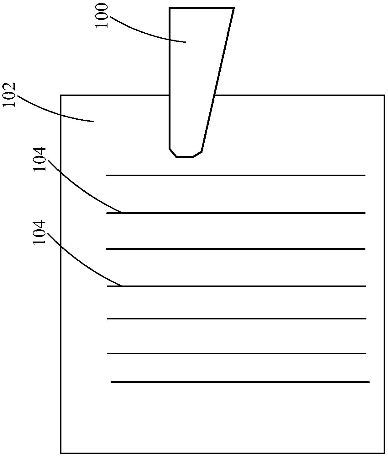
like figure 1 As shown, it depicts a schematic diagram of the clamping method of probes in the prior art. The micro probes 104 on the soft pad 102 are clamped with tweezers 100, which is laboriously clamped one by one manually, which is quite time-consuming. , it is easier to cause damage to the micro probe 104 because the manual clamping and applying force is not easy to control, thus resulting in defective products of the probe card (not shown) inserted with the probe 104

Method used


Image

  • Probe suction device
  • Probe suction device
  • Probe suction device

Examples


Embodiment Construction

[0021] Referring to the drawings, where the same reference numerals represent the same components or similar components, the principles of the present invention are exemplified when implemented in a suitable computing environment. The following description is based on illustrated specific embodiments of the invention, which should not be construed as limiting other specific embodiments of the invention not described in detail herein.

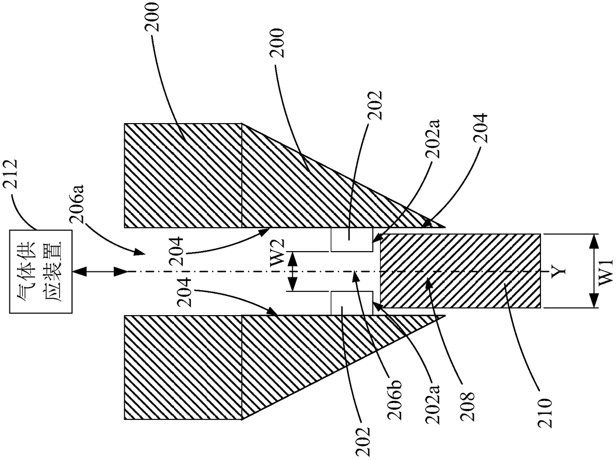
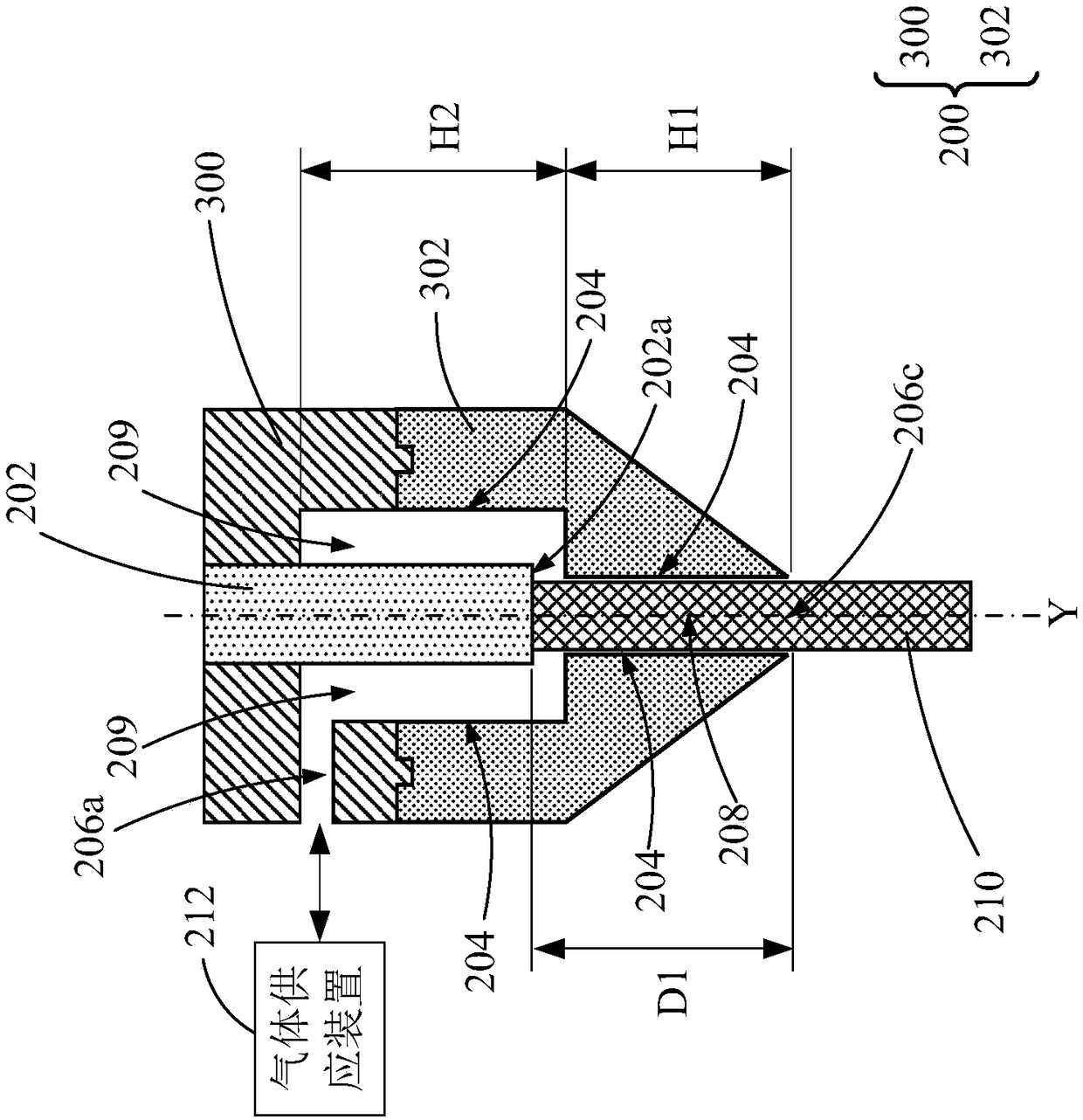
[0022] figure 2 A cross-sectional view of the probe suction device in the first embodiment of the present invention is shown. The probe suction device includes a body 200 and a stopper 202 . The body 200 has a sidewall surface 204 and a first opening 206a. The stopper 202 is fixed on the side wall surface 204, and the stopper 202 and the side wall surface 204 form a first receiving space 208, wherein the first opening 206a of the body 200 and the The first accommodating space 208 communicates, when the body 200 sucks the gas in the first acc...


PUM


Abstract

The present invention relates to a probe suction device comprising a body having a side wall surface and a first opening; and a stopper fixed to the side wall surface, the stopper and the side wall surface forming a first receiving space, wherein the first opening of the body is in communication with the first receiving space, and when the body sucks air in the first receiving space with the firstopening, the side wall surface of the body adsorbs a probe and one end of the stopper is abutted against the probe to allow the first receiving space to receive a portion of the probe.

Description

【Technical field】 [0001] The invention relates to a probe processing device, in particular to a probe suction device. 【Background technique】 [0002] With the development of electronic products towards precision and multi-functionality, the integrated circuit chips in electronic products tend to be more complex, and the pins required to test the current chips continue to increase, so the probes used to test the probe card of the chip The number has also increased significantly, and the processing efficiency of probes is extremely important. [0003] In the prior art, due to the small size of the micron needles of the probe card, there is no effective pick-and-place fixture for the clamping operation of the probe, and the probe can only be carried out manually with the help of tweezers and a microscope. gripping. Such as figure 1 As shown, it depicts a schematic diagram of the clamping method of probes in the prior art. The micro probes 104 on the soft pad 102 are clamped ...

Claims


Application Information

Patent Timeline
Patent Type & Authority Applications(China)
IPC IPC(8): G01R1/073
CPCG01R1/07392
Inventor 吕智韦沈毓达郑翰阳
Owner CHUNGHWA PRECISION TEST TECH
Learn More