
Material assembling vehicle

A technology for assembling vehicles and materials. It is used in transportation and packaging, mechanical conveyors, conveyors, etc., and can solve problems such as human injury, manual misoperation, and unfavorable structural stability.

Active Publication Date: 2021-09-07
SICC CO LTD
View PDF13 Cites 0 Cited by
  • Summary
  • Abstract
  • Description
  • Claims
  • Application Information

AI Technical Summary

Problems solved by technology

[0002] In the field of production and processing, it is usually necessary to transport materials. The traditional method of manual material handling not only consumes labor costs, but also may cause problems such as manual misoperation, manual contamination of materials, or human injury caused by material dust, which is not conducive to guarantee Safety in transit
[0003] In order to improve the above problems, there is an electric forklift capable of transporting materials in the prior art. The electric forklift is provided with a lifting device, which is used to place materials. When the electric forklift places materials on the platform of the target equipment, lifting The device carries the material to extend out of the main body of the electric forklift and toward the target equipment. When the material has a large weight, the center of gravity of the entire electric forklift will follow the action direction of the lifting device and detach from the main body of the electric forklift and lift it toward the target equipment. The movement direction of the device deviates, causing the connection structure between the lifting device and the main body of the electric forklift to be broken due to huge stress, or causing the instability of the material, causing the material to fall out of the lifting device, and even the electric forklift to roll over, which is not conducive to the structure stability

Method used


Image

  • Material assembling vehicle
  • Material assembling vehicle

Examples


Embodiment approach 1

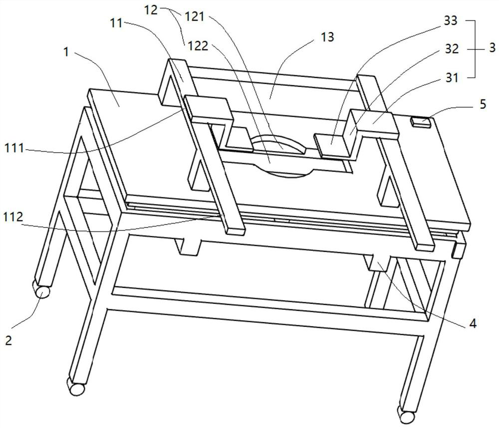
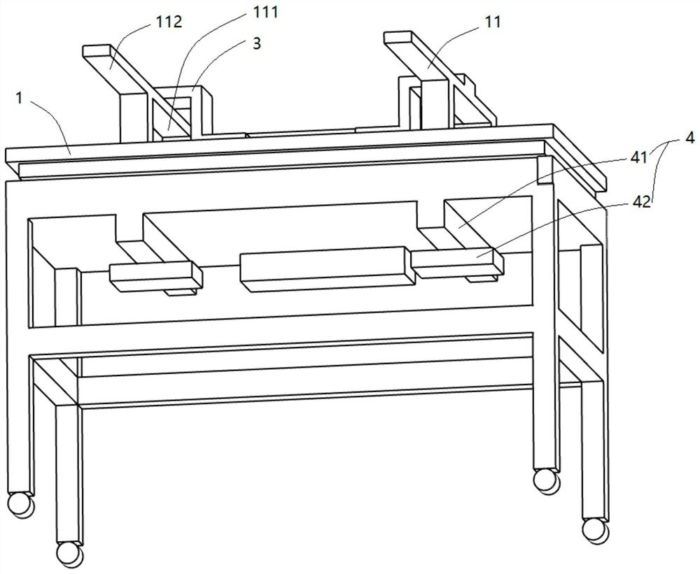
[0042] Implementation mode one: if figure 2 As shown, the driving element is a synchronous belt, the first sliding track 41 is formed on the synchronous belt, and is slidably and fixedly connected to the synchronous belt.

[0043] In this embodiment, the timing belt is connected to the motor, and the motor drives the timing belt to rotate. The slider 42 is fixedly connected to the timing belt, and the slider 42 is driven by the rotation of the timing belt. When 111 moves to the feeding end 112, the motor rotates forward and drives the synchronous belt to rotate, and drives the slider 42 to move in the opposite direction to the lifting mechanism 3, so that the center of gravity of the material platform 1 is stably placed on the material platform 1 along the material feeding The position of the center line in the given direction, when the lifting mechanism 3 moves from the feeding end 112 to the starting end 111, the motor reverses to drive the synchronous belt to rotate in the...

Embodiment approach 2

[0044] Embodiment 2: The driving member includes a cylinder connected to the motor and a push rod driven by the cylinder. The first sliding track 41 is formed on the surface of the material platform 1 , and the push rod can push the slider 42 to move relative to the first sliding track 41 .

[0045] In this embodiment, the cylinder is connected to the motor, and the push rod of the cylinder is connected to the slider 42 and can push the slider 42 to move along the first sliding track 41. When the lifting mechanism 3 moves from the starting end 111 of the extension arm 11 to the feeding end 112 At this time, the push rod pushes the slider 42 forward, and the pushing direction is opposite to the moving direction of the lifting mechanism 3, so as to stabilize the center of gravity on the centerline position of the material platform 1 along the material feeding direction. When the lifting mechanism 3 moves from the feeding end 112 to When the starting end 111 moves, the retraction ...


PUM


Abstract

The invention discloses a material assembling vehicle, and relates to the technical field of machining and production auxiliary equipment. The material assembling vehicle comprises a material platform, wheels, a lifting mechanism, a balance mechanism and a motor for driving the lifting mechanism and the balance mechanism. The material platform is provided with a containing groove and extension arms, and the lifting mechanism is slidably connected with the extension arms and can stretch into the containing groove to lift materials. The balance mechanism comprises first sliding rails which are horizontal to the extension direction of the extension arms, sliding blocks connected to the first sliding rails and a driving piece for driving the sliding blocks, and the sliding direction of the sliding blocks is opposite to the sliding direction of the lifting mechanism so that the gravity center of the material platform can be arranged at the center line position of the material platform in the material feeding direction. By arranging the balance mechanism, when the lifting mechanism does the feeding action of stretching out of the material platform, the balance mechanism moves in the direction opposite to the moving direction of the lifting mechanism, so that the gravity center shift caused by the position shift of the lifting mechanism is offset, and the gravity center of the material platform is stabilized.

Description

technical field [0001] The application relates to the technical field of processing and production auxiliary equipment, in particular to a material assembly vehicle. Background technique [0002] In the field of production and processing, it is usually necessary to transport materials. The traditional method of manual material handling not only consumes labor costs, but also may cause problems such as manual misoperation, manual contamination of materials, or human injury caused by material dust, which is not conducive to guarantee Safety in transit. [0003] In order to improve the above problems, there is an electric forklift capable of transporting materials in the prior art. The electric forklift is provided with a lifting device, which is used to place materials. When the electric forklift places materials on the platform of the target equipment, lifting The device carries the material to extend out of the main body of the electric forklift and toward the target equipm...

Claims


Application Information

Patent Timeline
IPC IPC(8): B65G35/00
CPCB65G35/00
Inventor 沈安宇苏丽娜
Owner SICC CO LTD
Learn More