
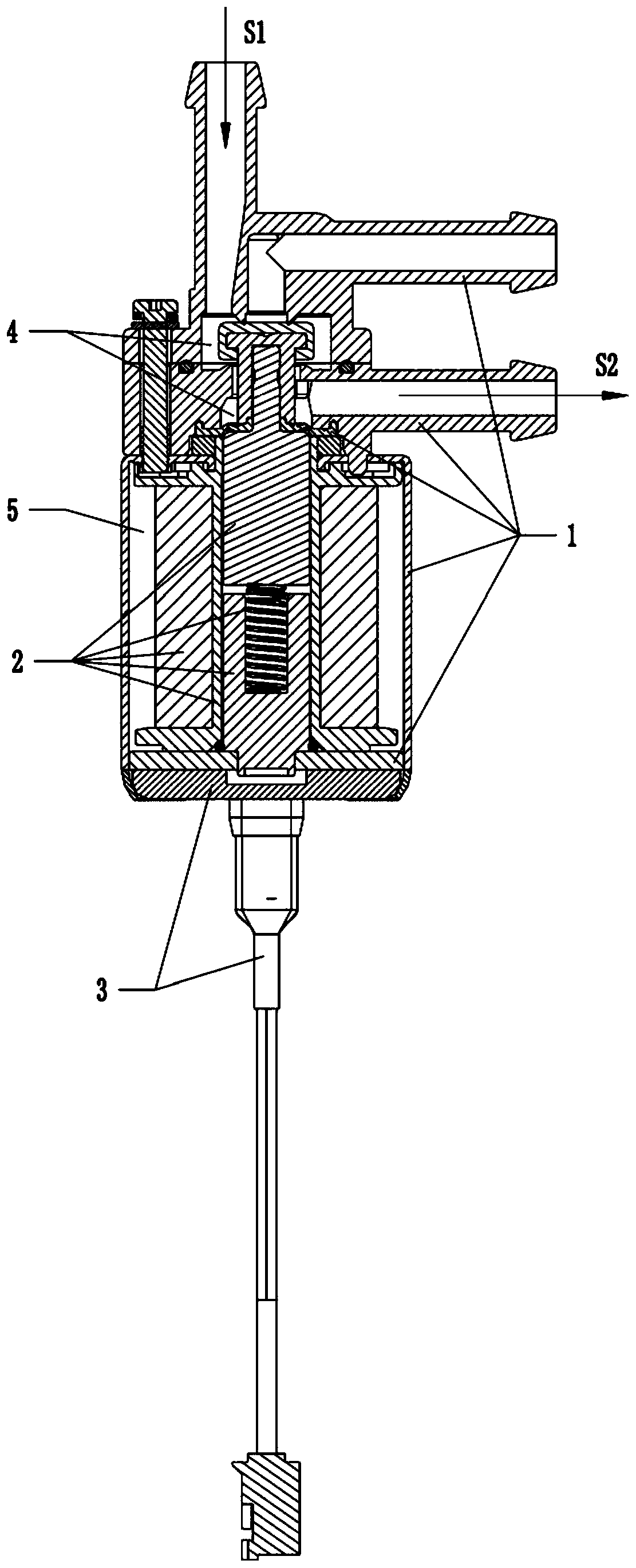
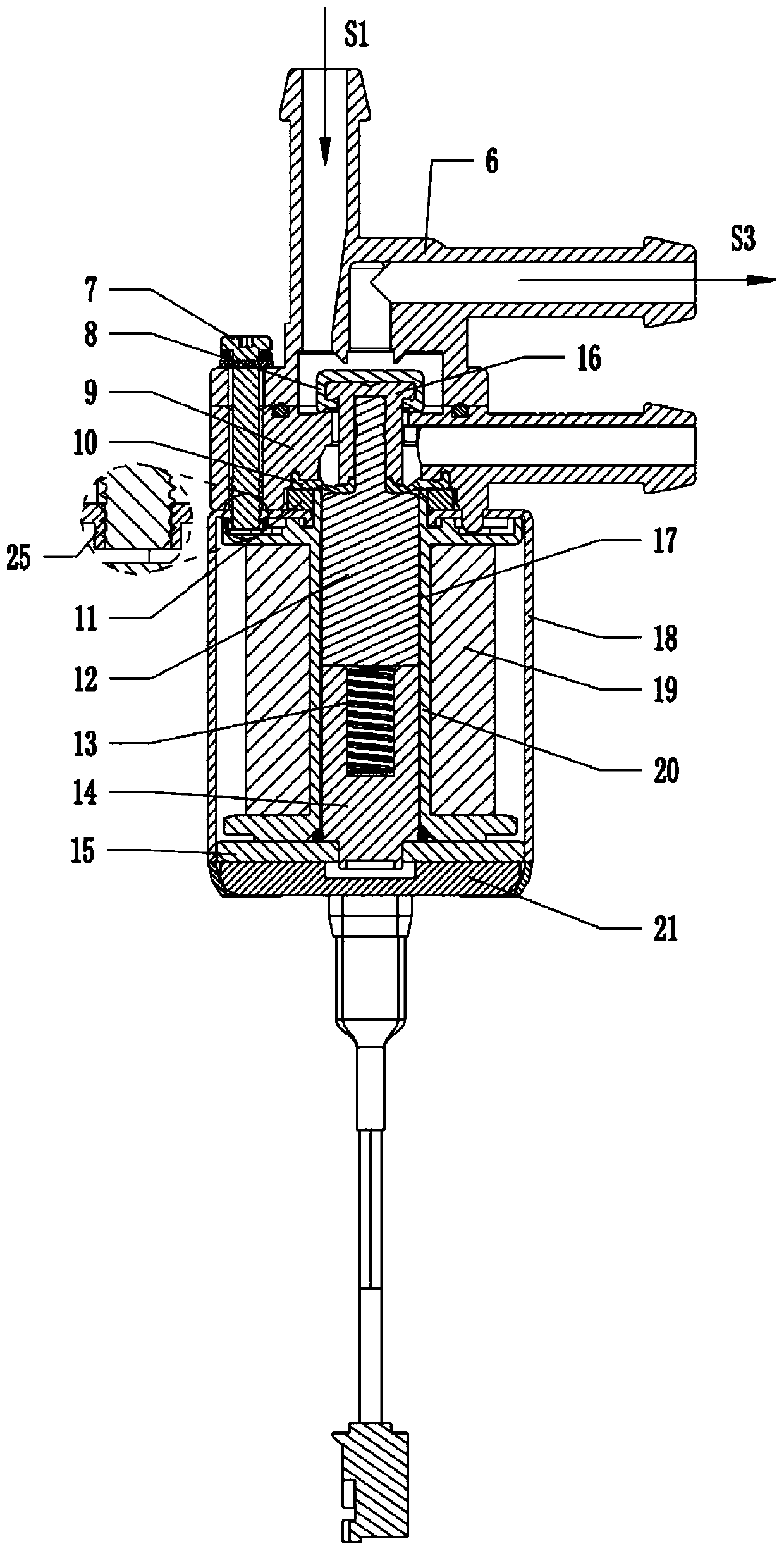
Electromagnetic diaphragm valve

A diaphragm valve and electromagnetic technology, applied in valve details, multi-port valves, valve devices, etc., can solve the problem of affecting the change of the moving valve core or the reliability of the switching path, affecting the airtight reliability of the electromagnetic diaphragm valve, and affecting the switching of the moving valve core. problems such as access reliability, to achieve the effect of fast riveting process, simple riveting process, and guaranteed reliability

Pending Publication Date: 2019-10-22
XIAMEN CONJOIN ELECTRONICS TECH
View PDF0 Cites 0 Cited by
  • Summary
  • Abstract
  • Description
  • Claims
  • Application Information

AI Technical Summary

Problems solved by technology

Due to the long-term working process of the electromagnetic diaphragm valve, the movable spool will move up and down repeatedly, resulting in the change of the electromagnetic drive mechanism in the up and down direction relative to the shell mechanism, which will not only affect the change of the movable spool or the reliability of the switching path. performance, and even affect the airtight reliability of the electromagnetic diaphragm valve
At the same time, the electromagnetic diaphragm valve in the prior art has multiple positioning references in the positioning of the up and down direction, which greatly increases the tolerance of the electromagnetic diaphragm valve in the up and down direction, which further affects the reliability of the dynamic valve core change or switching path

Method used


Image

  • Electromagnetic diaphragm valve
  • Electromagnetic diaphragm valve
  • Electromagnetic diaphragm valve

Examples


Embodiment Construction

[0030] In order to make the purpose, technical solutions and advantages of the embodiments of the present invention clearer, the technical solutions in the embodiments of the present invention will be clearly and completely described below in conjunction with the accompanying drawings in the embodiments of the present invention. Obviously, the described embodiments It is some embodiments of the present invention, but not all of them. Based on the implementation manners in the present invention, all other implementation manners obtained by persons of ordinary skill in the art without creative efforts fall within the protection scope of the present invention. Accordingly, the following detailed description of the embodiments of the invention provided in the accompanying drawings is not intended to limit the scope of the claimed invention, but merely represents selected embodiments of the invention. Based on the implementation manners in the present invention, all other implement...


PUM


Abstract

The invention provides an electromagnetic diaphragm valve and relates to the technical field of diaphragm valves. The electromagnetic diaphragm valve comprises a shell mechanism, an electromagnetic drive mechanism and a lead mechanism. Specifically, the shell mechanism comprises an outer shell, a middle cover, an upper cover, a lower cover and a diaphragm sandwiched between the outer shell and themiddle cover, wherein a solution cavity is formed between the middle cover and the upper cover, a liquid feeding section and a first liquid discharge section of the upper cover and a second liquid discharge section of the middle cover communicate with the solution cavity, the outer shell is provided with a tubular section, a support surface and a spin riveting surface, and the middle cover is supported by the support surface; the electromagnetic drive mechanism includes a static valve element, a movable valve element, a sealing sleeve and an elastic member; the lead mechanism includes a support seat supported by the spin riveting surface and used for supporting the lower cover; the static valve element can attract the moving valve element and drive the sealing sleeve to move downward so as to enable the liquid feeding section and the first liquid discharge section to communicate and compress the elastic member; and the elastic member can drive the movable valve element and drive the sealing sleeve to move upward, so as to enable the liquid feed section and the second liquid discharge section to communicate.

Description

technical field [0001] The invention relates to the technical field of diaphragm valves, in particular to an electromagnetic diaphragm valve. Background technique [0002] The diaphragm valve is a valve body that uses a diaphragm as an opening and closing part to close the flow channel, cut off the fluid, and separate the inner cavity of the valve body from the inner cavity of the bonnet. The electromagnetic diaphragm valve is a diaphragm valve that drives the seal to change or switch the passage through an electrical signal. [0003] Electromagnetic diaphragm valves generally include a shell mechanism and an electromagnetic drive mechanism. The electromagnetic drive mechanism has a moving valve core and a static valve core. During specific work, the static valve core can attract the moving valve core to move up and down to change or switch channels. Due to the long-term working process of the electromagnetic diaphragm valve, the movable spool will move up and down repeated...

Claims


Application Information

Patent Timeline
Patent Type & Authority Applications(China)
IPC IPC(8): F16K11/044F16K27/02F16K31/06
CPCF16K11/044F16K27/0263F16K27/029F16K31/0627F16K31/0675
Inventor 颜宏
Owner XIAMEN CONJOIN ELECTRONICS TECH
Learn More