Circularly polarized antenna for product testing and testing system

A circularly polarized antenna and product testing technology, which is applied to the structural connection of antennas and antenna grounding switches, and devices that enable antennas to work in different bands at the same time, can solve the problems of high axial ratio bandwidth antennas, poor antenna axial ratio bandwidth, and poor Comply with circular polarization and other issues, achieve good axial ratio characteristics, increase axial ratio bandwidth, and improve axial ratio bandwidth

Active Publication Date: 2019-10-22
GOERTEK INC
View PDF10 Cites 0 Cited by
  • Summary
  • Abstract
  • Description
  • Claims
  • Application Information

AI Technical Summary

Problems solved by technology

In the prior art, it is difficult to design a wideband axial ratio bandwidth antenna. For example, if the Vivaldi antenna meets the requirements of circular polarization, two radiating elements need to be set orthogonally, and the phase difference between the two ports is set to 90 degrees to meet the above requirements. The required design is very complicated. In addition, there is another kind of circularly polarized antenna designed by the Archimedes antenna. There are two rotationally symmetrical Archimedes spirals and one Archimedes spiral on the substrate. The end is connected to the feeder. Although the axial ratio bandwidth of the antenna is better in the low frequency band, but in the high frequency band, the axial ratio bandwidth of the antenna is poor, which does not meet the requirements of circular polarization.

Method used


Image

  • Circularly polarized antenna for product testing and testing system
  • Circularly polarized antenna for product testing and testing system
  • Circularly polarized antenna for product testing and testing system

Examples


Embodiment Construction

[0027] The following will clearly and completely describe the technical solutions in the embodiments of the present invention in conjunction with the accompanying drawings in the embodiments of the present invention. Obviously, the described embodiments are only some of the embodiments of the present invention, not all of them. Based on the embodiments of the present invention, all other embodiments obtained by persons of ordinary skill in the art without making creative efforts belong to the protection scope of the present invention.

[0028] The core of the present invention is to provide a circularly polarized antenna and a test system for product testing, which are used to meet the requirements of circular polarization with better axial ratio bandwidth at the same time in the low frequency band and high frequency band.

[0029] In order to enable those skilled in the art to better understand the solution of the present invention, the present invention will be further descri...


PUM


Abstract

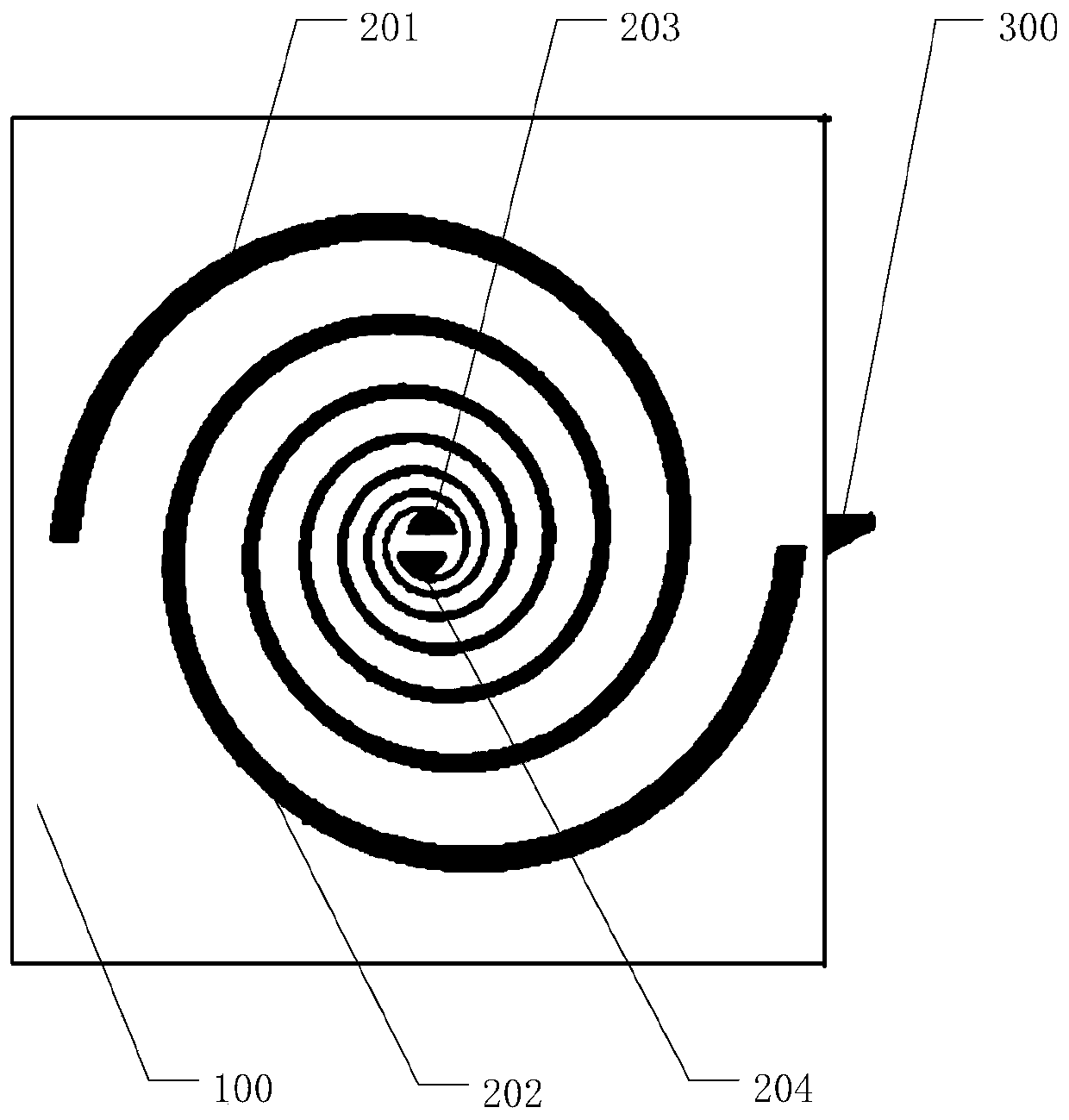
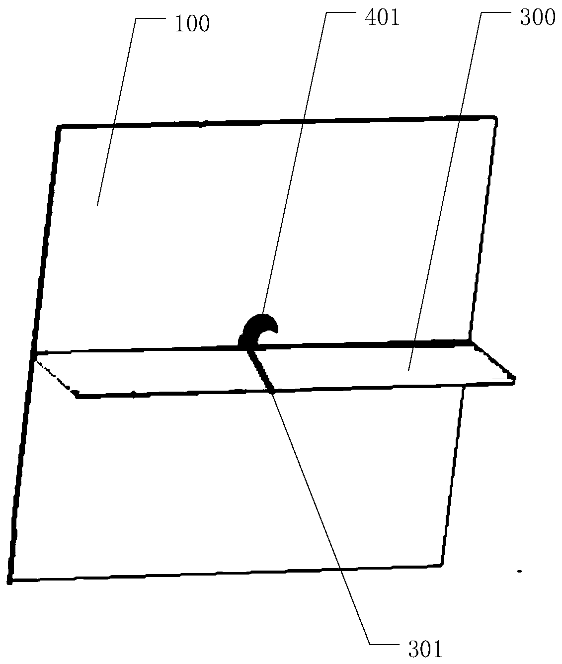
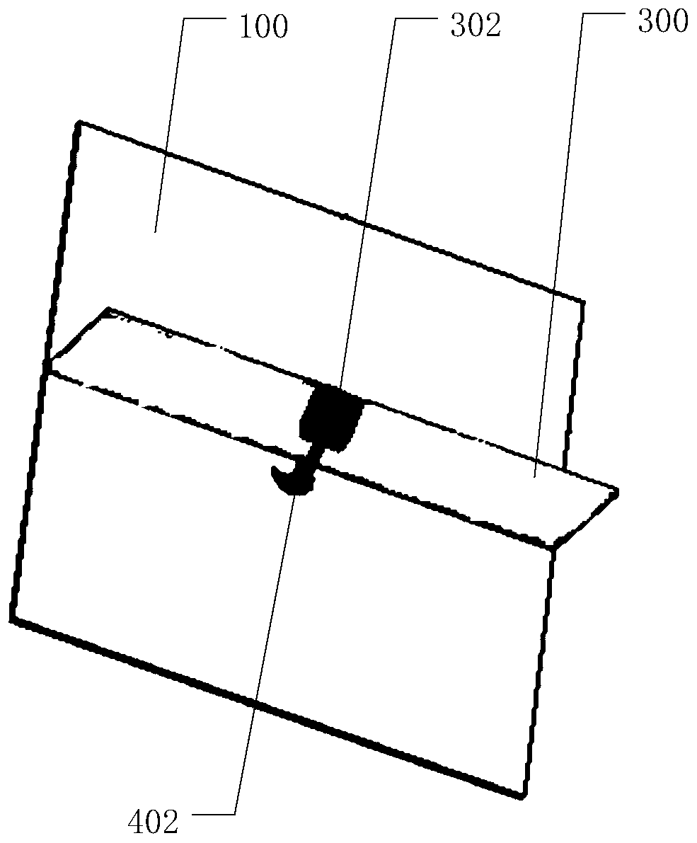
The invention discloses a circularly polarized antenna for product testing and a testing system. The front surface of a substrate of the antenna is provided with two Archimedes spirals in rotational symmetry; the back surface of the substrate is provided with a symmetric excitation pair for exciting an antenna pattern on the front surface of the substrate; and a feeding part of the antenna is realized through an adapter plate perpendicular to the back surface of the substrate. As the symmetric excitation pair has a gradual shape, circularly polarized radiation higher than 2.4 GHz can be excited, the problem that the Archimedes spiral center part pattern is difficult to adjust is remedied, and the axis ratio bandwidth is thus increased. Thus, the antenna can have good axis ratio characteristics in a low frequency band and can also have good axis ratio characteristics in a high frequency band, and thus, the axis ratio bandwidth of the antenna is improved to a great extent. Besides, the above structure is simple and easy to realize. In addition, the testing system disclosed in the invention comprises the above antenna with the above effects.

Description

technical field [0001] The invention relates to the radio field, in particular to a circularly polarized antenna and a test system for product testing. Background technique [0002] In wireless communication, there are two kinds of test antennas, one is a circularly polarized antenna synthesized by linear polarization, and the other is a helical antenna. These two types of antennas have two common features: one is frequency-invariant, that is, the antenna response curve does not change with frequency; the other is circular polarization. The above two features can meet general requirements, and are applicable to products of different frequency bands or products of different forms. [0003] The axial ratio means that the endpoint locus of the instantaneous electric field vector of any polarized wave is an ellipse, and the ratio of the major axis 2A to the minor axis 2B of the ellipse is called the axial ratio AR (Axial Ratio). The axial ratio is an important performance inde...

Claims


Application Information

Patent Timeline
IPC IPC(8): H01Q1/38H01Q1/50H01Q5/20H01Q5/307
CPCH01Q1/38H01Q1/50H01Q5/20H01Q5/307
Inventor 何其娟
Owner GOERTEK INC
Why Eureka
Try Eureka