Steam condensation device and cooking utensil

A technology of steam condensation and steam cooling, which is applied to cooking utensil lids, cooking utensils, household utensils, etc. It can solve the problems of steam temperature, large amount of steam, scalding people, unable to cool the condensation cavity, etc., achieving good effect and convenient recycling Effect

Active Publication Date: 2019-10-25
JOYOUNG CO LTD
View PDF7 Cites 6 Cited by
  • Summary
  • Abstract
  • Description
  • Claims
  • Application Information

AI Technical Summary

Problems solved by technology

With this structure, the cold air only partially enters the cooling condensing cavity, and the steam temperature and steam volume in the cooling condensing cavity are relatively large, so it cannot cool down well in the cooling condensing cavity. The internal wind speed is fast and the volume is small, so the steam will be taken out quickly, and its cooling effect is average. In actual use, the temperature of the discharged steam is still h...

Method used


Image

  • Steam condensation device and cooking utensil
  • Steam condensation device and cooking utensil
  • Steam condensation device and cooking utensil

Examples


Embodiment 1

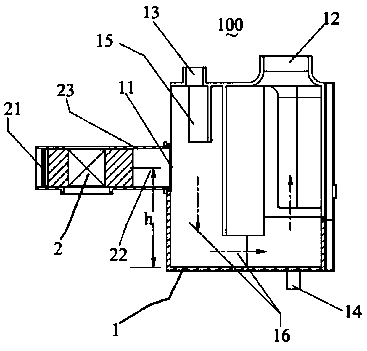
[0036] see figure 1As shown, the first embodiment of a steam condensing device 100 of the present invention includes a cooling mixing chamber 1, a fan 2 for accelerating steam cooling, and the cooling mixing chamber 1 is provided with an air inlet 11, an exhaust port 12, a first steam Inlet 13 and drain port 14 , the first steam inlet 13 introduces steam into the cooling mixing chamber 1 , and the drain port 14 is arranged at the bottom of the cooling mixing chamber 1 . The fan 2 is provided with an air inlet 21 and an air outlet 22. The cold air blown out by the air outlet 22 enters the cooling mixing chamber 1 through the air inlet 11 and mixes with the steam for cooling, and the cooled gas is discharged out of the condensation device through the air outlet 12.

[0037] As a preferred embodiment, the cooling mixing chamber 1 is made of metal or plastic, and the air inlet 11 is arranged on the side wall of the cooling mixing chamber 1 and is located in the middle, so as to pr...

Embodiment 2

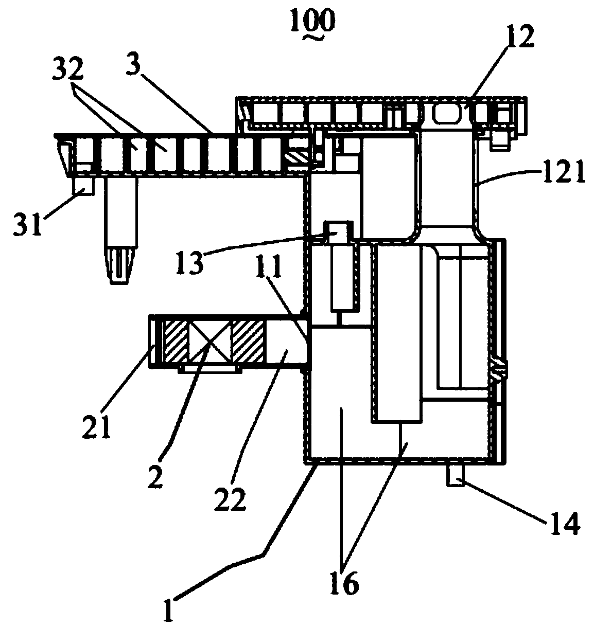
[0055] see figure 2 As shown, the second embodiment of the present invention adds a cooling buffer chamber 3 on the basis of Embodiment 1, the cooling buffer chamber is arranged at the front end of the first steam inlet 13, and the cooling buffer chamber is provided with a second steam inlet 31, To introduce steam into the cooling buffer chamber 3 , the first steam inlet 13 communicates with the cooling buffer chamber 3 to introduce the steam in the cooling buffer chamber into the cooling mixing chamber 1 .

[0056] In this embodiment, the cooling buffer chamber 3 is arranged at the front end of the first steam inlet 13 to perform preliminary cooling and buffer reserve for the steam entering the cooling mixing chamber, so as to avoid the injection of cold air into the cooling mixing chamber and affect the front end. Steam heating or front-end heating effect.

[0057] As an improved embodiment, the cooling and buffer chamber 3 is also provided with a drain hole (not shown in ...

Embodiment 3

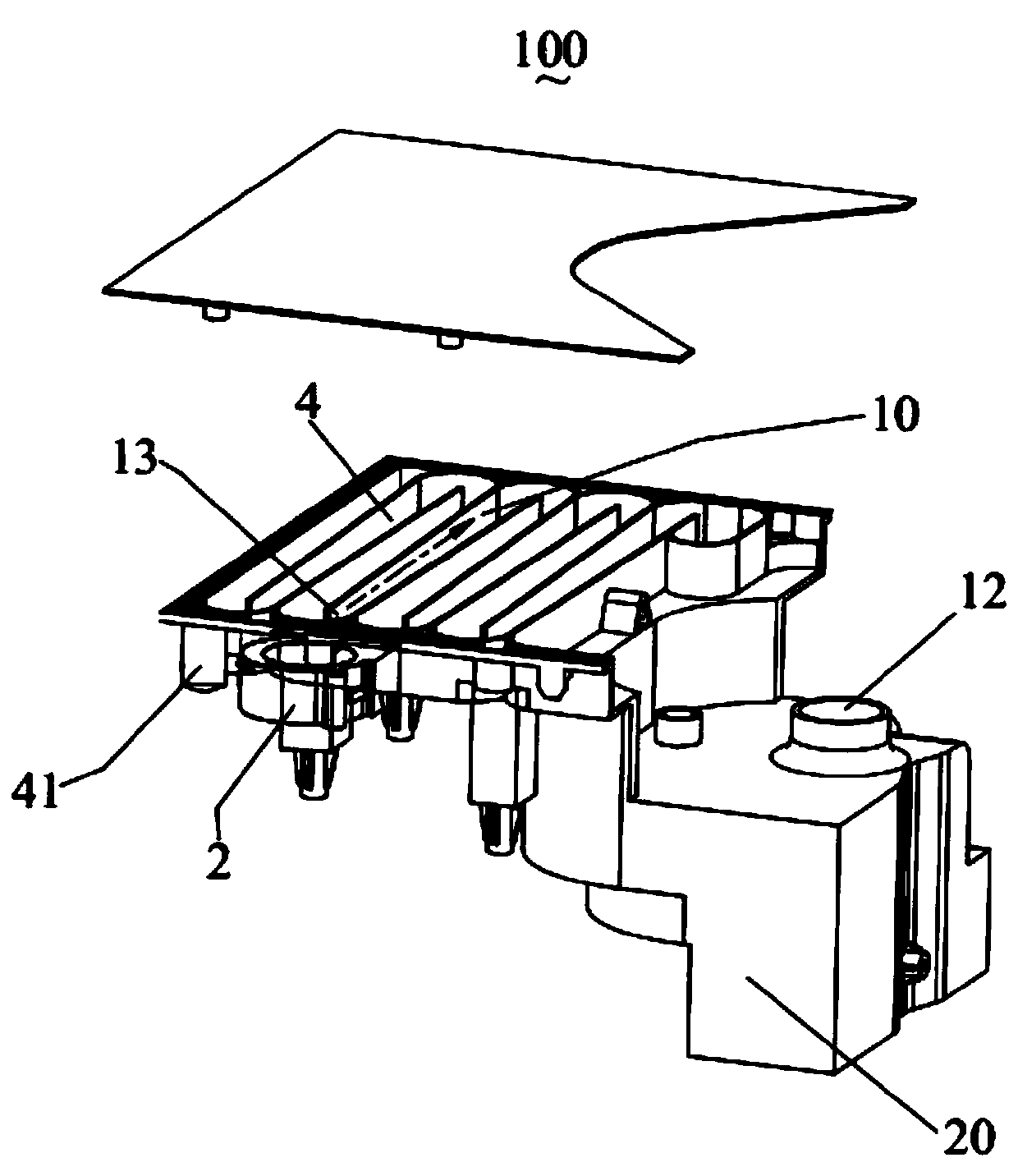
[0065] see image 3 As shown, the fourth embodiment of the present invention is improved on the basis of the first embodiment. The cooling mixing chamber 1 includes a first mixing part 10 formed by a steam introduction pipe 4, and a second mixing part 20. The first steam The inlet is the boundary between the steam introduction pipe and the first mixing part. That is to say, a third steam introduction port 41 is provided at the front end of the steam introduction pipeline for steam introduction flow, and the rear end of the steam introduction pipeline 4 forms the first mixing part 10 of the cooling mixing chamber, and the mixing, exhaust, structures such as drainage.

[0066] As a preferred embodiment, the shape of the second mixing part is consistent with the first embodiment. The air inlet is arranged in the first mixing part 10 . In this embodiment, the steam leading pipe is used to form a part of the cooling mixing chamber, which enlarges the effective cooling path of th...


PUM


Abstract

The invention discloses a steam condensation device. The device comprises a cooling mixing cavity and a fan for accelerating steam cooling. The cooling mixing cavity is provided with an air inlet, anair outlet, a first steam inlet and a water outlet. The steam is guided into the cooling mixing cavity through the first steam inlet. The water outlet is formed in the bottom of the cooling mixing cavity, the fan is provided with an air suction port and an air outlet, cold air blown out of the air outlet completely enters the cooling mixing cavity through the air inlet to be mixed with the steam for cooling, and cooled gas is exhausted out of the cooling mixing cavity through the air outlet. According to the steam condensation device, steam condensate water can be conveniently recycled. The invention further discloses a cooking utensil.

Description

technical field [0001] The invention relates to the field of kitchen appliances, in particular to a steam condensing device and a cooking appliance with the steam condensing device. Background technique [0002] Rice cookers and pressure cookers are essential items in the kitchen. The taste of the food they cook is unanimously recognized by everyone. However, during the cooking process, they need to discharge a lot of steam, which may cause the risk of polluting the kitchen environment and may burn the user. [0003] A steam condensing device has appeared in the prior art. The main structure is to set a condensing chamber for introducing steam, such as the condensing device disclosed in CN206151259U, which blows the condensing chamber through a fan to condense the steam in the condensing chamber. The focus of this structure is to cool the condensing cavity, rather than directly condensing the steam. The cooling effect is average, and a large amount of steam is still discharg...

Claims


Application Information

Patent Timeline
IPC IPC(8): A47J27/00A47J27/08A47J36/06A47J36/00
CPCA47J27/00A47J27/08A47J36/00A47J36/06
Inventor 朱泽春于凌振邱雄杰
Owner JOYOUNG CO LTD
Why Eureka
Try Eureka