
Trough-type mixing machine

A trough mixer and mixing hopper technology, which is applied to mixers, mixers with rotating stirring devices, mixer accessories, etc., can solve the problems of increasing production costs, material waste, and material scattering, so as to avoid waste and reduce production cost, and the effect of reducing scatter

Inactive Publication Date: 2019-10-25
NANJING HUAXING PHARMA EQUIP
View PDF0 Cites 0 Cited by
  • Summary
  • Abstract
  • Description
  • Claims
  • Application Information

AI Technical Summary

Problems solved by technology

[0002] The structure of the existing trough mixer includes a mixing hopper, an agitator and a motor. The agitator is arranged in the mixing hopper, and the shaft of the agitator is connected to the motor. Rotate to mix the materials evenly. After the mixing is completed, the materials are poured out by turning over the mixing hopper. Although the trough mixer with this structure can effectively mix the materials, it is easy to scatter the materials when the mixing hopper pours them out, resulting in Material waste, increased production costs

Method used

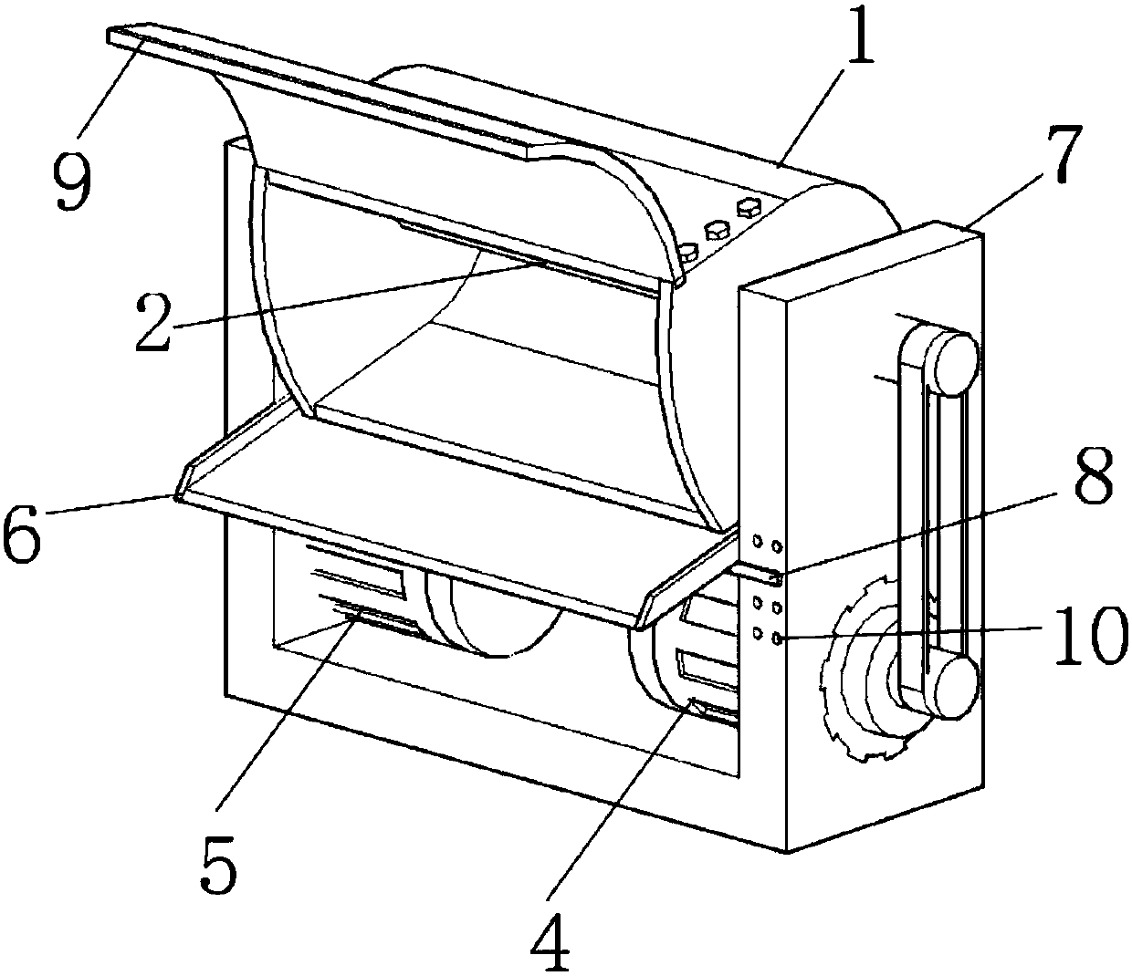
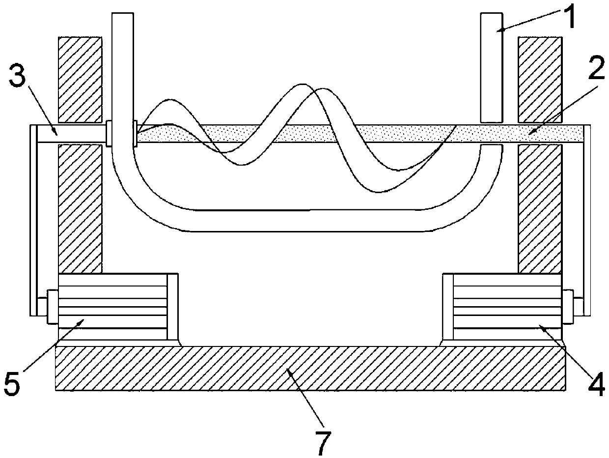
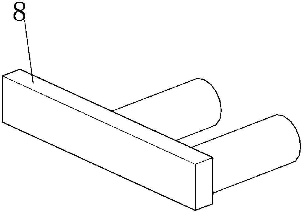

Image

  • Trough-type mixing machine
  • Trough-type mixing machine
  • Trough-type mixing machine

Examples


Embodiment Construction

[0022] Such as figure 1 , figure 2 and image 3 As shown, the trough mixer includes a mixing hopper 1, an agitator 2, a first motor 4, a second motor 5 and a support 7, the agitator 2 is arranged in the mixing hopper 1, and the shaft of the agitator 2 is connected to the mixing hopper 1 One end of the shaft of the agitator 2 runs through the side of the mixing hopper 1 and is rotatably connected with the bracket 7. One end of the mixing hopper 1 is fixed with a turning shaft 3, and the turning shaft 3 is rotatably connected with the bracket 7. The first motor 4 and the second motor 5 are located below the mixing hopper 1, the first motor 4 is connected to the shaft end of the agitator 2, the second motor 5 is connected to the turning shaft 3, and one side of the mixing hopper 1 is provided with a discharge tray 6 . Wherein, the first motor 4 is connected to the shaft end of the agitator 2 through a transmission belt, and the second motor 5 is connected to the turning shaft...


PUM


Abstract

The invention provides a trough-type mixing machine, and belongs to the field of trough-type mixing machines. The trough-type mixing machine comprises a mixing hopper, a stirrer, motors and a support,the stirrer is arranged in the mixing hopper, a shaft of the stirrer is rotatably connected with the side face of the mixing hopper, one end of the shaft of the stirrer penetrates through the side face of the mixing hopper and is rotatably connected with the support, a turn-over shaft is fixed to one end of the mixing hopper and rotatably connected with the support, the first motor and the secondmotor are arranged below the mixing hopper, the first motor is connected with the end of the shaft of the stirrer, the second motor is connected with the turn-over shaft, a pouring disc is arranged on one side of the mixing hopper, the two sides of one end of the pouring disc are hinged to the support, and limiting blocks are arranged on the two sides of the lower part of the pouring disc; and the side face of the support is provided with a plurality of limiting holes from top to bottom, one ends of the limiting blocks are movably connected with the limiting holes, and the other ends of the limiting blocks are located on the lower part of the pouring disc. Scattering of materials during pouring is reduced so as to save the production cost, and the discharge height can be changed.

Description

technical field [0001] The invention belongs to the field of groove mixers, and in particular relates to a groove mixer. Background technique [0002] The structure of the existing trough mixer includes a mixing hopper, an agitator and a motor. The agitator is arranged in the mixing hopper, and the shaft of the agitator is connected to the motor. Rotate to mix the materials evenly. After the mixing is completed, the materials are poured out by turning over the mixing hopper. Although the trough mixer with this structure can effectively mix the materials, it is easy to scatter the materials when the mixing hopper pours them out, resulting in Material waste increases production costs. [0003] In view of the deficiencies in the prior art, it is now necessary to provide a trough mixer that can reduce the scattering of materials when pouring out, so as to save production costs, and can change the discharge height. Contents of the invention [0004] The object of the present ...

Claims


Application Information

Patent Timeline
Patent Type & Authority Applications(China)
IPC IPC(8): B01F7/08B01F15/02
CPCB01F27/72B01F35/751
Inventor 吴修兵
Owner NANJING HUAXING PHARMA EQUIP
Learn More