Coating method of light-emitting diode fluorescent powder

A phosphor and LED chip technology, applied in electrical components, circuits, semiconductor devices, etc., can solve the problems of difficult selection of dam colloids, difficult implementation of packaging links, limited application scope, etc., to reduce light loss and achieve high transparency. , the effect of wide applicability

Inactive Publication Date: 2010-07-28
江苏米优光电科技有限公司
View PDF1 Cites 23 Cited by
  • Summary
  • Abstract
  • Description
  • Claims
  • Application Information

AI Technical Summary

Problems solved by technology

[0004] Lumileds' technology is basically based on flip-chip technology. Given that high-power chips are currently mainly mounted or vertical structures, their application range is limited.
Osram's technology is mainly chip technology, which is very difficult to realize in the packaging process, and the unique TAG phosphor used by Osram is different from the general YAG phosphor, so it is also difficult to implement
Cree's "dam" technology for vertically structured chips is more suitable for the packaging of high-power LED chips on the market, but its very specific printed circuit board or tube socket design, metal composition and structure design, and surrounding The choice of dam colloid is difficult for ordinary LED packaging companies

Method used


Image

  • Coating method of light-emitting diode fluorescent powder
  • Coating method of light-emitting diode fluorescent powder
  • Coating method of light-emitting diode fluorescent powder

Examples


Embodiment 1

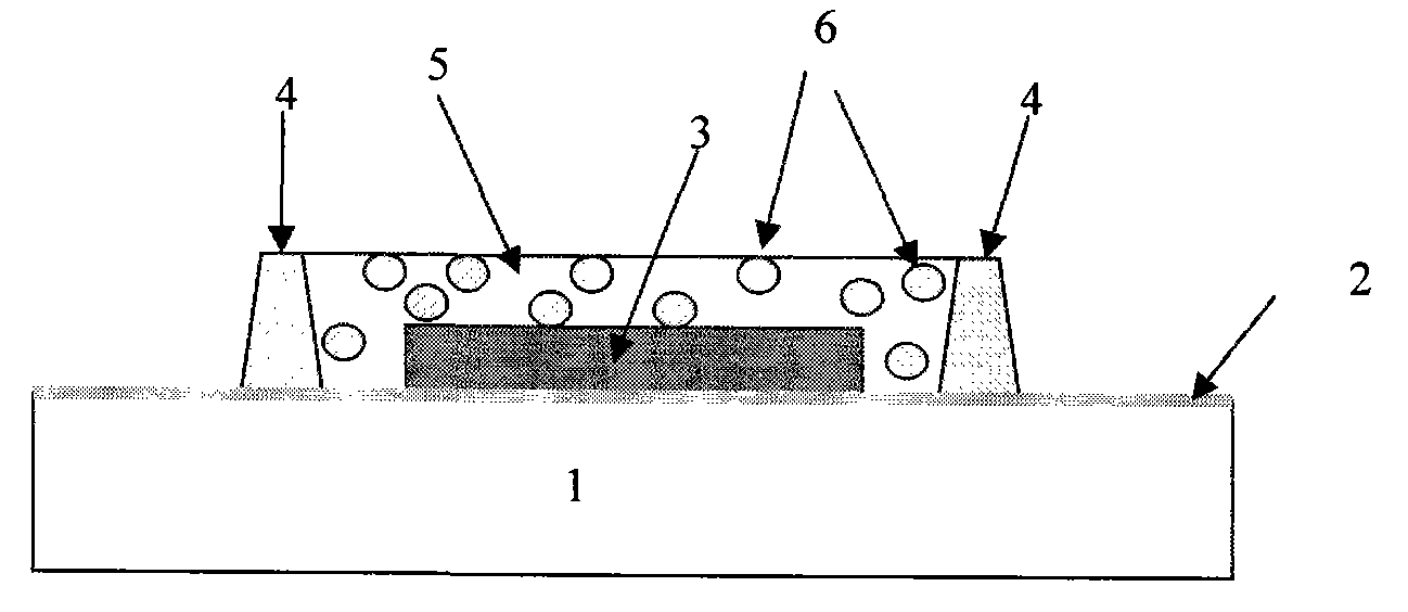
[0049]The invention provides a technique for partially coating fluorescent powder on an LED chip. After the LED chip is solidified and wire-bonded on the power-type bracket, the precision automatic dispensing equipment with a robotic arm is used to draw a colloid "dam" around the chip. The glue used is visible light transparent glue, and the Ag reflection of the reflective bowl The layer is not wetted, and its fluidity is reduced by using nano-SiO2 material. Formed colloidal "dams" are formed by heat curing or UV curing. Then dot an appropriate amount of fluorescent powder glue in the middle of the dam. Curing again to obtain LEDs with phosphor powder partially coated on the chip.

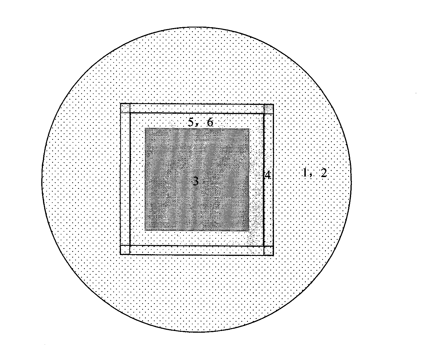
[0050] Figure 1a It is a cross-sectional structure diagram of phosphor powder partially coated on the LED chip. Ag reflector 2 is plated on the heat sink 1 of the power LED bracket, and the base material of the heat sink is generally Cu. The power LED chip 3 is fixed on the Ag surface of the he...

Embodiment 2

[0071] Embodiment 1 illustrates a typical implementation method of the present invention. However, in some special cases, higher requirements are placed on the reliability of the coated phosphor. Therefore a second embodiment is given. Such as Figure 3a , shown in 3b, it differs from Embodiment 1 in that a layer of Si resin 6' is added between the chip 3 and the phosphor adhesive layer 5,6, in order to ensure the uniformity of the thickness of the protective layer Si resin 6', We added an additional 4' of dam.

[0072] In this embodiment, the specific preparation steps of the coating method of LED phosphor powder are as follows:

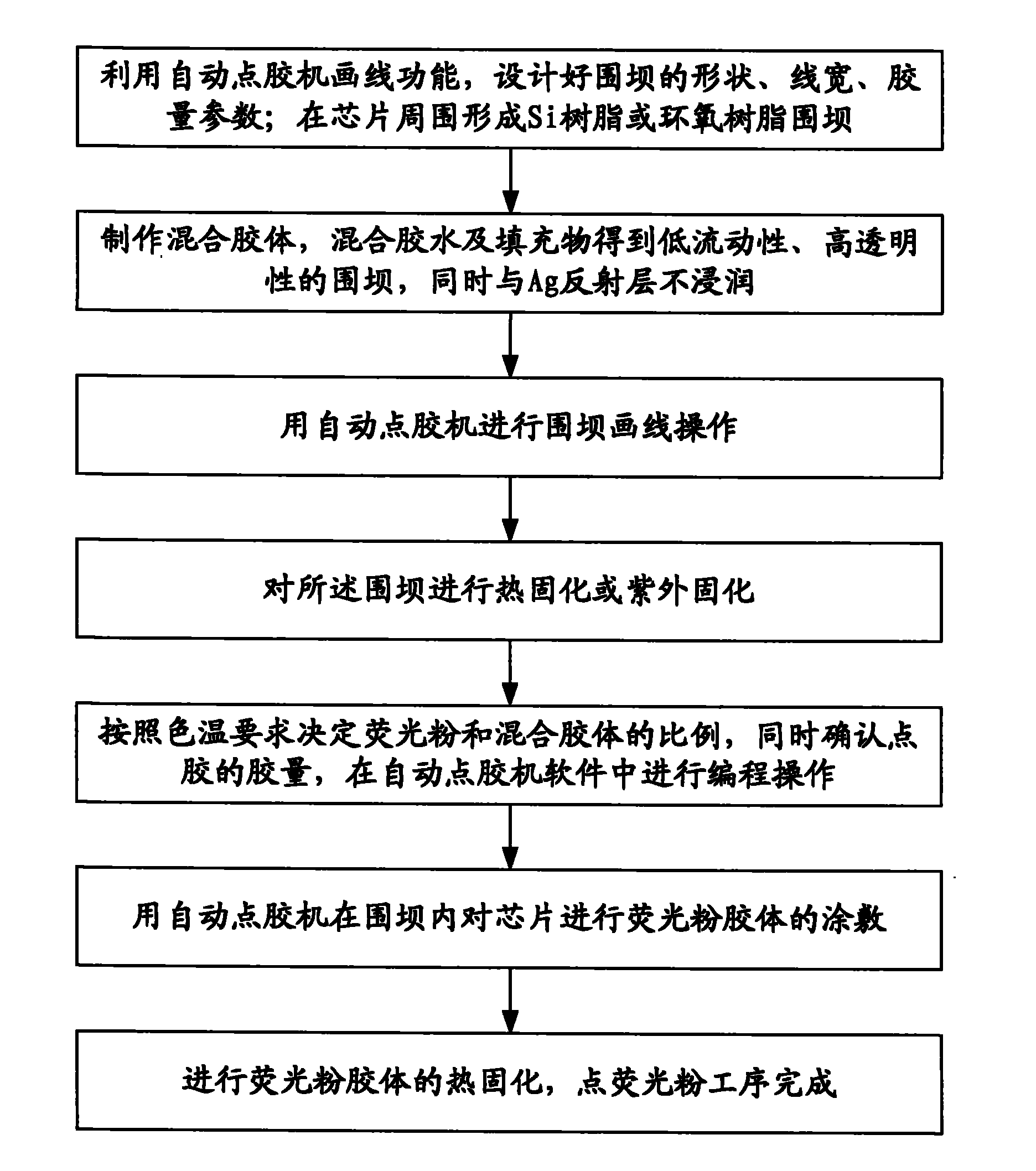
[0073] (1) Use the "line drawing" function of the automatic glue dispenser to design the shape of the dam shown in Figure 3, the line width, the amount of glue and other parameters. Two dams are formed around the chip, and the height and width of the dam close to the chip are smaller than the outer "dam". The height of the inner layer "dam" is ...

Embodiment 3

[0084] With the improvement of LED chip manufacturing and packaging level, multi-chip integration has become an important direction of packaging applications. Therefore, we give a third embodiment based on multi-chip local phosphor glue dispensing. Such as Figure 4a , 4b As shown, it is different from Embodiment 1 in that it realizes the "dam" of multi-chips. For specific preparation steps, please refer to Example 1.

[0085] For multi-chip packaging, due to the mutual mixing of excitation light and fluorescence between chips, the yellow circle measured by ordinary dispensing methods is not obvious, which meets the requirements for ordinary lighting. However, when the liquid crystal display has strict requirements on the thickness of the backlight source, the local color difference will still affect the display quality. Therefore, this problem can be solved in the form of multi-chip dam packaging. For multi-chip dams, since adjacent chip dams can be shared, the number of ...


PUM


Abstract

The invention discloses a coating method of light-emitting diode (LED) fluorescent powder. The method comprises the following steps: performing crystal- bonding and wire-bonding of a LED chip on a support, using a precision automatic adhesive-dispensing device with a robot arm to draw colloidal box dam around the chip; forming a colloidal box dam through hot curing or ultraviolet curing; dispensing a defined amount of fluorescent powder adhesive in the box dam; and curing again to obtain the LED, wherein fluorescent powder is coated on part of the chip. By using the method of the invention, the uniformity of light colour of the white LED can be increased; and the adhesive thickness round the chip can be accurately controlled by using the box dam, thus the effect of white light-mixing in all directions is controlled, and yellow ring, blue ring and other non-uniform phenomena can not appear.

Description

technical field [0001] The invention belongs to the technical field of LED encapsulation, and relates to a method for encapsulating a white light LED, in particular to a method for coating phosphor powder of a power type white light LED. Background technique [0002] LED (Light Emitting Diode), light-emitting diode, is a solid-state semiconductor device that can directly convert electricity into light. White light LED refers to mixing three primary color LEDs into white light through a certain light intensity ratio, or converting monochromatic LEDs into white light LEDs through phosphor powder technology. Recently, there are LED chips that directly emit white light through different light-emitting active layers. At present, the commonly used white light LED preparation method in the market is to obtain white light by mixing phosphor powder with blue light or purple light emitted by the LED. Usually phosphor powder is mixed with epoxy resin or silicone resin, and then coated...

Claims


Application Information

Patent Timeline
Patent Type & Authority Applications(China)
IPC IPC(8): H01L33/48H01L33/50
Inventor 宋金德陈志忠张茂胜董维胜张国义
Owner 江苏米优光电科技有限公司
Why Eureka
Try Eureka