Diffuser for flat panel display

a flat panel display and diffuser technology, applied in the field of optical sheet materials, can solve the problems of lack of dimensional stability, coating defects, defect generation, etc., and achieve the effect of preventing discoloration

Active Publication Date: 2008-01-01
SABIC GLOBAL TECH BV
View PDF16 Cites 23 Cited by
  • Summary
  • Abstract
  • Description
  • Claims
  • Application Information

AI Technical Summary

Benefits of technology

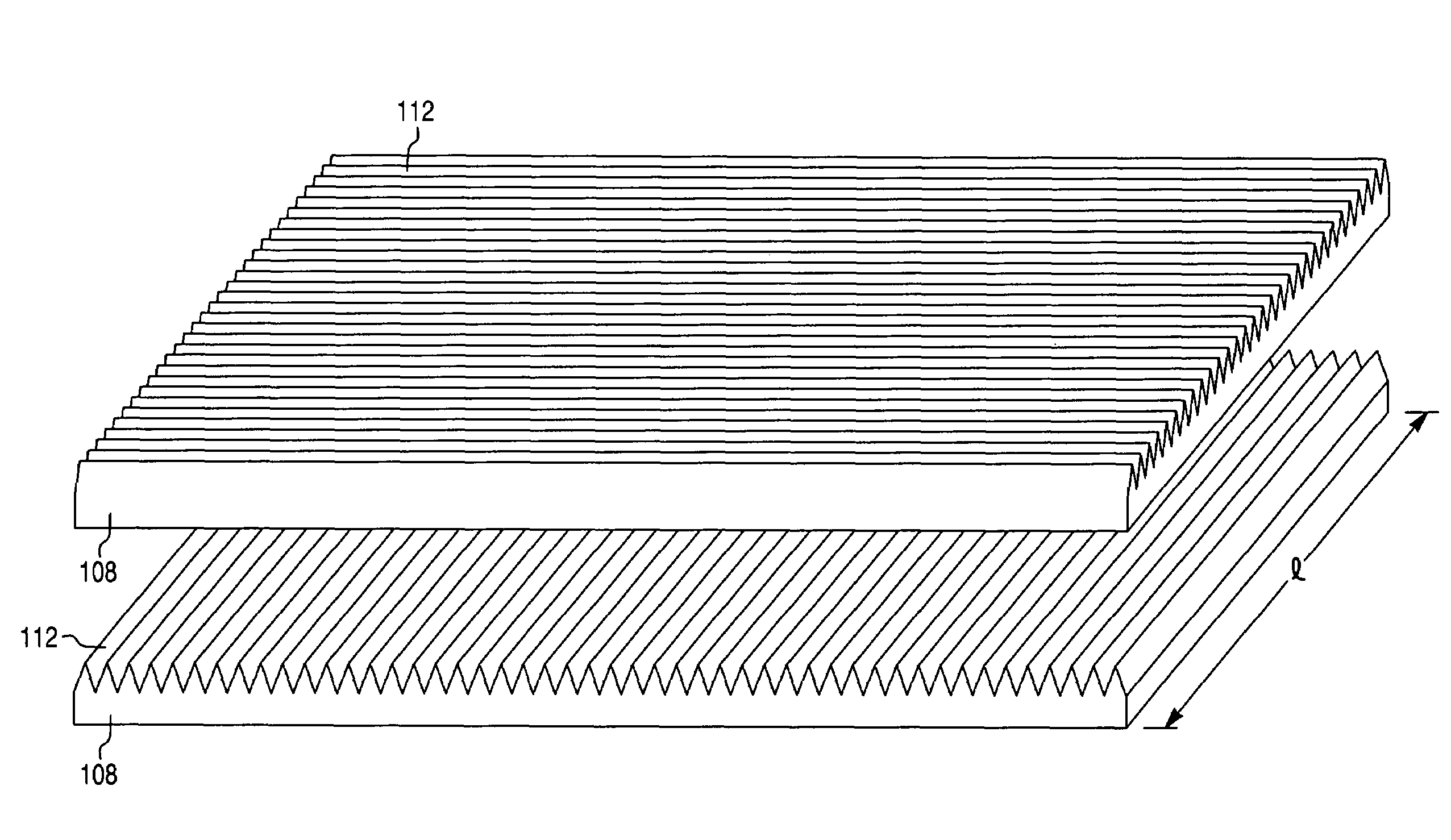
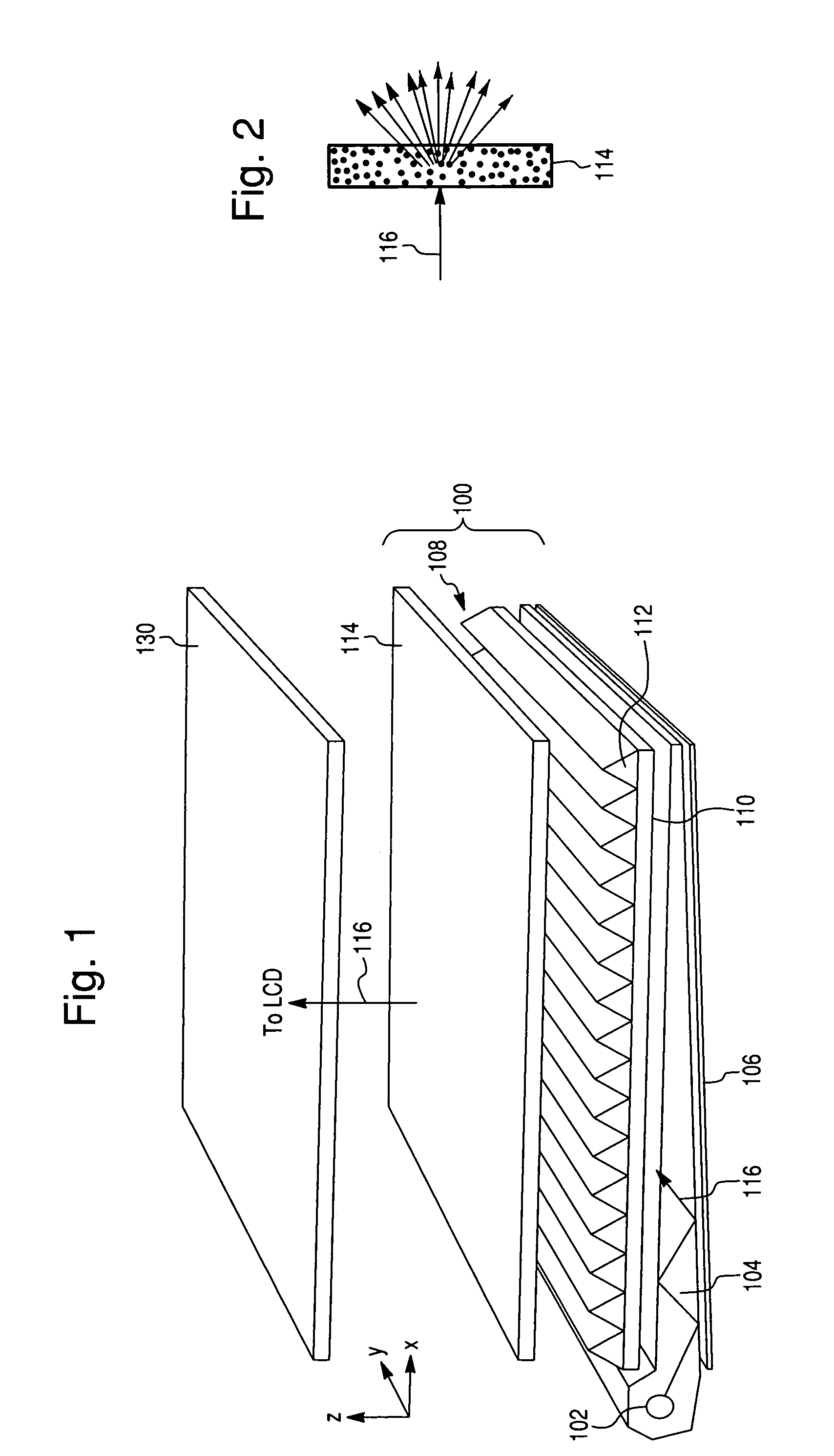
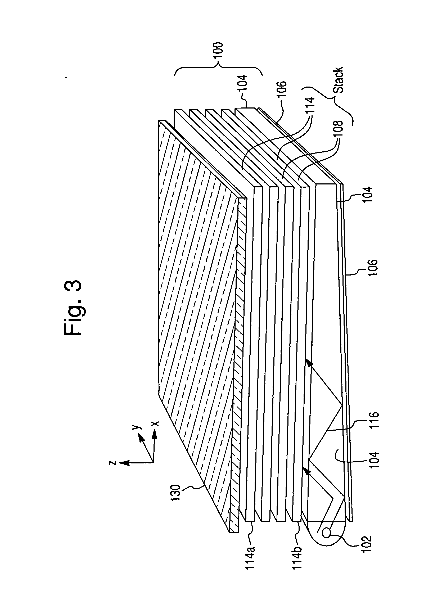
[0007]An embodiment of the invention features a light diffusing film with a low scattering power hereinafter referred to as a top diffuser film or a light diffusing film with a high scattering power hereafter referred to as a bottom diffuser film. Desirably both films are unitary or monolithic films characterized by the absence of coatings and include a uniformly dispersed anti-static material comprising a fluorinated phosphonium sulfonate in an amount sufficient to impart anti-static properties to the film. The films may also contain at least one UV stabilizer to prevent discoloration due to the short wavelength light coming out of the light source. The top diffuser film consists essentially of polycarbonate material and the anti-static material and has a texture on at least one surface thereof for obtaining a low scattering of light. The bottom diffuser film consists essentially of polycarbonate, the anti-static material, possibly a UV stabilizer, and a uniformly dispersed acrylic bulk scattering additive having a particle size of from about 3 to about 10 microns in an amount from about 2 to about 7 percent by weight percent for the high scattering of light.
[0022]In another aspect of the invention there is provided a light diffusing film. The film comprises: a polycarbonate material; and an ultraviolet absorber (UVA) component in an effective amount to reduce discoloration of the film when exposed to ultraviolet (UV) light, wherein the color shift of the film after 200 hours of accelerated weathering according to the ASTM D4674 method 3 is dx<0.0005 and dy<0.0005, where dx is the shift in the x chromaticity coordinate and dy is the shift in the y chromaticity coordinate according to CIE 1931, and wherein the color shift is measured in reflectance mode using a D65 illuminant and an observer angle of 10°.

Problems solved by technology

Some of undesirable features of diffuser films are a lack of dimensional stability during high temperature and humidity testing due to mismatched material properties between the substrate and coating, coating defects due to lack of coating process robustness, defect generation during material conversion due to scratches in the coatings, impressions or texture non-uniformities due to tooling and / or web handling rollers, dust attraction and film stickage due to static charge creation, and reduced luminance and luminance uniformity.
The first four of the above undesirable features may reduce the yield during the various cutting and assembly processes.

Method used


Image

  • Diffuser for flat panel display
  • Diffuser for flat panel display
  • Diffuser for flat panel display

Examples


examples

[0069]The top protective diffusing film requires a very low light scattering power film. This is due to the fact that the luminance that the viewer detects is inversely proportional to the scattering power of the film. The description below outlines the product performance and method of manufacture of a top protective diffuser according to embodiments of the invention.

example # 1

Example #1

Top Diffusing Film

[0070]A state of the art extrusion line (extruder, melt pump, film die, and calendaring roll stack) was used to produce a top protective diffuser product. A chrome plated steel calendaring roll was used, polished to less than 1 μin Ra (Ra is the surface roughness), and a silicone rubber backing roll was used. The polymer resin used was LEXAN EXRL0080-1111 (described in U.S. Pat. No. 6,194,497 to Henricus et al. and available from GE Plastics) with the FC-1 antistatic additive incorporated at a level of between 0.5 and 1.5 mass

Operating conditions included:

[0071]Barrel zone temperatures: 450-550° F.[0072]Mass flow rate: 200-250 lbs / hr[0073]Die zone temperatures: 520-530° F.[0074]Die lip width: 68 inches[0075]Calendaring roll setup:[0076]Roll Position 1: Textured (40 μin Ra nominal) Silicone 0.375 inch thick nominal, 70 Shore A durometer nominal.[0077]Roll Position 2: Polished ([0078]Nip pressure: 30-200 psi (15-150 pli)[0079]Film thickness: 0.005 inch

Chart...

example # 2

Example #2

For Bottom Diffusing Film

[0083]The bottom diffusing film requires a very high light scattering power film. This is to hide features from the light guide and help make the light more uniform. The description below outlines the product performance and method of manufacture of a bottom diffuser.

[0084]A state of the art optical film extrusion line (extruder, melt pump, film die, and calendaring roll stack) was used to produce a bottom diffuser product. A chrome plated steel calendaring roll was used produced using a slow blast texturing process, and a silicone rubber backing roll was used. The polymer resin used was LEXAN EXRL0091-WH5A201X (available from GE Plastics) which has an optimal acrylic bulk scattering additive at a loading of approximately 3-5% and size of 3-7 microns. Again the FC-1 antistatic additive was incorporated at a level of between 0.5 and 1.5 mass %. The polymer particles enhance the diffusing power of the film in conjunction with the textured surfaces. B...


PUM

PropertyMeasurementUnit
hazeaaaaaaaaaa
surface resistivityaaaaaaaaaa
hazeaaaaaaaaaa

Abstract

A light diffusing film for a back light display is described. The light diffusing film includes a unitary film consisting essentially of polycarbonate and a uniformly dispersed anti-static material in an amount sufficient to impart anti-static properties to the film. The anti-static material may comprise a fluorinated phosphonium sulfonate. The film may additionally include at least one textured surface for the low scattering of light. Alternatively, the film may additionally include a uniformly dispersed acrylic bulk scattering additive of particles having a mean particle size of from about 3 to about 10 microns and present in an amount from about 2 to about 7 percent by weight percent for the high scattering of light.

Description

RELATED APPLICATIONS[0001]This application claims is related to and claims priority from U.S. provisional application 60 / 451,342 filed on Feb. 28, 2003, the entire contents of which are incorporated by reference.BACKGROUND OF THE INVENTION[0002]This invention relates to optical sheet material and, more specifically, to such sheet material characterized by light diffusion properties. This invention also relates to back light displaying using the optical sheet, and to processes for making the sheet material.[0003]In many current displays systems, for example in Liquid Crystal Displays (LCD), it is desirable to have diffusing components. Examples of the utility of diffusing components include (but are not limited to) masking artifacts, such as seeing electronic components located behind the diffuser film and / or hiding injection molded patterns or printing on the light guide pipe of the display, improved uniformity in illumination and increased viewing angle. In a typical LCD display, d...

Claims


Application Information

Patent Timeline
Patent Type & Authority Patents(United States)
IPC IPC(8): G02F1/335C08K5/50C08L69/00F21V8/00G02B5/02G02B5/04G02F1/13357
CPCG02B5/0231G02B5/0242G02B5/0268G02B5/0278G02B6/0051G02B5/045Y10T428/1064G02F2001/133607Y10T428/10C09K2323/051C09K2323/00G02F1/133607G02B5/02C08J5/18G02F1/1335
Inventor HAY, GRANTCAPALDO, KEVIN P.COJOCARIU, GHEORGHEKUMAR, KARKALA ARUNHOEKS, THEODORUS LAMBERTUSLOEHR, TODD M.GRAF, JOHN F.HOFFMAN, NATHAN D.LESLIE, SCOTTGHOSAL, ANSHUSCHOTTLAND, PHILIPPE
Owner SABIC GLOBAL TECH BV
Why Eureka
Try Eureka