Catadioptric reduction lens

a reduction lens and catadioptric technology, applied in the field of catadioptric projection lenses, can solve the problems of large volume, difficult to provide purely refractive systems that have been sufficiently well corrected for chromatic aberration, and difficult to fabricate such mirror systems. , to achieve the effect of reducing the quantity of materials required

Inactive Publication Date: 2006-02-28
CARL ZEISS SMT GMBH
View PDF35 Cites 24 Cited by
  • Summary
  • Abstract
  • Description
  • Claims
  • Application Information

AI Technical Summary

Benefits of technology

[0028]A projection lens in the sense of the invention that is of the type mentioned at the outset hereof is characterised in that its second, dioptric section, which starts behind the final reflective surface of its beam-deflecting device, has at least one lens arranged between said final reflective surface and its intermediate image. Said intermediate image thus lies within its second, exclusively refractive, section in order that at least one of the lenses of said second section that precede said intermediate image in the optical train may contribute to creating said intermediate image. The invention thus foresees that the distance between said final reflective surface of said beam-deflecting device and said intermediate image will be considerable, which may allow, e.g., creating an accessible intermediate image in order to, e.g., allow installing a field stop in order to reduce stray-light levels. It will be particularly beneficial if that large distance will provide that said final reflective surface lies in a zone where the beam diameter is rather large, which will provide for its uniform illumination while avoiding hazardous, localized, peaks in radiant intensity and spread any heating of the optical element to which said reflective surface has been applied over a larger area, which will, in turn, improve its imaging performance. More important, however, is that any minor flaws that may be present on its reflective surface will have only a negligible, or no, effect on the qualities of images projected onto the image plane. Lenses with high imaging performance may thus be constructed, in spite of the minimal demands on the uniformity and figure of said final reflective surface.
[0031]The aforementioned benefits apply regardless of whether a lens is arranged between said final reflective surface and said real intermediate image, largely due to the large distance between same. Said distance, which shall hereinafter also be referred to as the “intermediate-image distance,” should preferably be chosen such that the diameter of the beam at a surface orthogonal to said optical axis at the intersection of said final reflective surface with said optical axis will be at least 10% of the diameter of said concave mirror, e.g., 17% or more of said diameter. However, said distance should not be so large that said ratio of the diameter of said beam to the diameter of said concave mirror will be much greater than 20% or 25% in order to confine the field curvatures that will need to be corrected to manageable levels. Said large intermediate-image distance will allow arranging said at least one lens between said final reflective surface and said real intermediate image, where said lens or lenses will preferably have a positive refractive power or powers, which will keep the diameter of those lenses that follow said intermediate image small, which, in turn, will allow designing said second section in manners that will allow reducing the quantities of materials required.
[0032]Arranging at least one lens between said final reflective surface and said real intermediate image also provides hitherto unknown opportunities for minimizing, or totally eliminating, the deleterious effects of lens heating. In order to reduce or preclude same, a preferred embodiment of the invention has a front intermediate-image lens arranged on its object side, ahead of said intermediate image, and a rear intermediate-image lens arranged on its image side, behind said intermediate image, where said intermediate-image lenses are symmetrically arranged with respect to said intermediate image such that any asymmetric contributions to imaging errors, such as coma, caused by heating of said intermediate-image lenses will be partially compensated, even nearly fully compensated, as shall be discussed in greater detail in terms of the sample embodiments to be discussed below.
[0034]Obtaining the favorable arrangement of said intermediate image according to the invention will be simplified if said first, catadioptric section does not contribute, or does not materially contribute, to the overall reduction ratio of said projection lens. Said catadioptric first section of said projection lens should preferably have a magnifications, βM, that exceed 0.95 and preferred embodiments of same will have magnifications of βM>1, i.e., will create enlarged intermediate images, which will facilitate shifting same to said refractive second section.
[0036]Preferred embodiments of the invention will provide that that surface of that lens of said refractive section that lies closest to said intermediate image will be spherical. However, the surfaces of both lenses facing said intermediate image might also be spherical, which will allow fabricating lenses with high imaging performances and low scatter in their imaging performances without need for imposing extremely stringent tolerances on same, since the figuring accuracies attainable during fabrication are generally better for spherical surfaces than for aspherical surfaces, which also may exhibit transmittance gradients and excessive surface microroughnesses. On the other hand, those surfaces in the vicinity of intermediate images have extremely strongly impacts on corrections for imaging errors, such as distortion, which is why conventional lens designs frequently employ aspherical surfaces near intermediate images. However, in the case of those projection lenses considered here, it will be preferable to employ lenses with high-precision, nearly perfectly accurately figurable, spherical surfaces in the vicinity of said intermediate image.

Problems solved by technology

However, there are very few materials, in particular, synthetic quartz glass and crystalline fluorides, such as calcium fluoride, magnesium fluoride, barium fluoride, lithium fluoride, lithium calcium aluminum fluoride, lithium strontium aluminum fluoride, and similar, that are sufficiently transparent in that wavelength region available for fabricating the optical elements required.
Since the Abbé numbers of those materials that are available lie rather close to one another, it is difficult to provide purely refractive systems that have been sufficiently well-corrected for chromatic aberrations.
Although this problem could be solved by employing purely reflective systems, fabricating such mirror systems requires substantial expense and effort.
The disadvantage of employing such systems is that hardly any suitable transparent materials are available in the desired, large volumes.
Moreover, fabricating optically active beamsplitter coatings situated within beamsplitter cubes is extremely difficult.
Heating effects occurring within beamsplitters may also present problems at high radiant intensities, since inside the beamsplitters an intermediate image is created.
However, none of these documents makes any statements regarding heating problems that might arise or how they may be avoided.
However, such systems have the disadvantage that they are, by virtue of their design, necessarily off-axis systems.
One of their disadvantages is that even the slightest flaws on any of their reflective surfaces may adversely affect the qualities of images projected onto their image plane.
Moreover, their focusing of radiant energy onto reflective surfaces may cause heating effects that might adversely affect their imaging performance.
The resultant, locally high, radiant intensities may also damage the reflective coatings that are normally applied to the surfaces of mirror blanks.

Method used


Image

  • Catadioptric reduction lens
  • Catadioptric reduction lens
  • Catadioptric reduction lens

Examples


Embodiment Construction

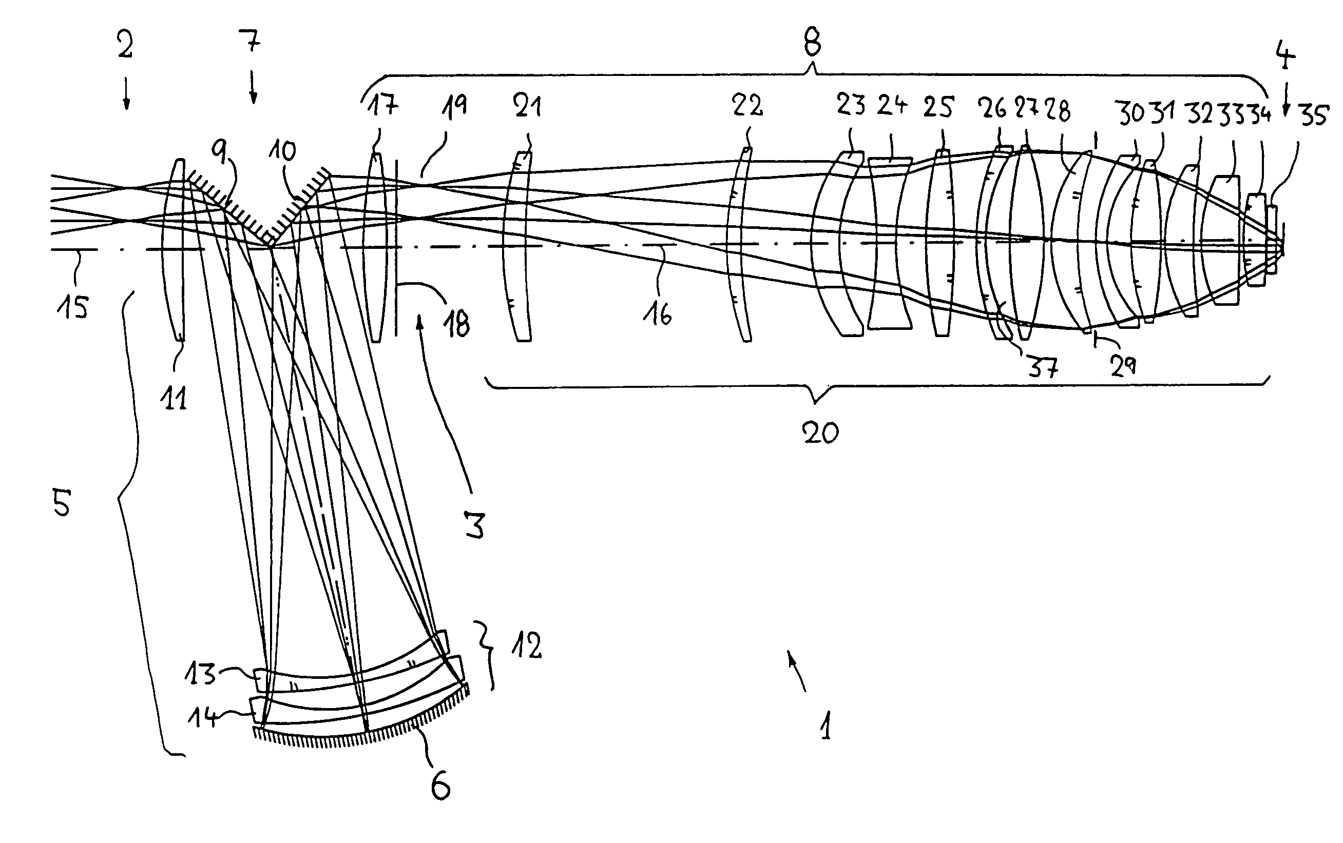
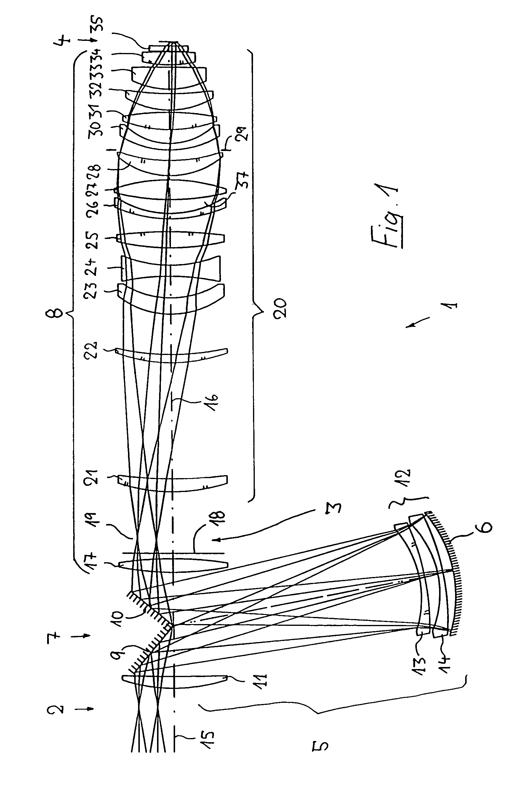
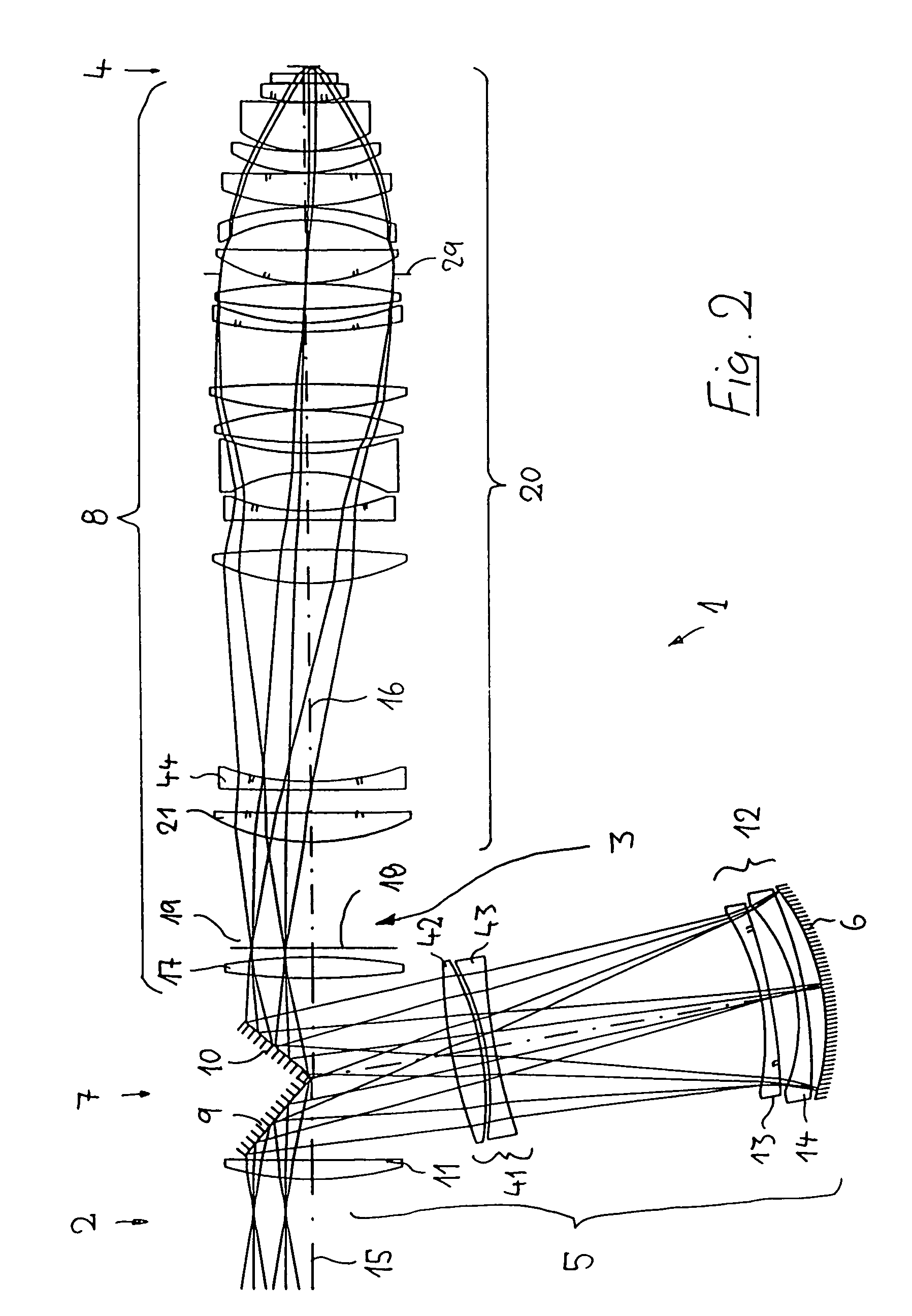
[0043]In the following description of preferred embodiments of the invention, the term “optical axis” refers to a straight line or a sequence of straight-line segments passing through the centers of curvature of the optical elements involved, where said optical axis will be folded at the reflective surfaces of deflecting mirrors or other reflective optical elements. Directions and distances shall be designated as “image-side” directions or distances if they are directed toward either the image plane involved or a substrate to be illuminated that is present in said plane and as “object-side” directions or distances if they are directed along that segment of said optical axis extending toward the object involved. In the case of those examples presented here, said object may be either a mask (reticle) bearing the pattern of an integrated circuit or some other pattern, such as a grating. In the case of those examples presented here, the image of said object is projected onto a wafer coa...


PUM

PropertyMeasurementUnit
wavelength rangeaaaaaaaaaa
wavelengthsaaaaaaaaaa

Abstract

A catadioptric projection lens configured for imaging a pattern arranged in an object plane (2) onto an image plane (4) while creating a single, real, intermediate image (3) has a catadioptric imaging group (5) having a concave mirror (6) and a beam-deflector (7), and a dioptric imaging lens group (20) that commences after the beam-deflector. The system is configured such that the intermediate image follows the first lens (17) of a dioptric section (8) and is preferably readily accessible. Arranging the intermediate image both between a pair of lenses (17, 21) of the dioptric section and at a large distance behind the final reflective surface of the beam-deflector helps to avoid imaging aberrations.

Description

[0001]This application is a Continuation of application Ser. No. 10 / 152,290 filed May 22, 2002, now U.S. Pat. No. 6,717,746 the disclosure of which is incorporated herein by reference, and this application claims the benefit of U.S. Provisional Application No. 60 / 530,622, filed Dec. 19, 2003. Priority is claimed from German Patent Application No. 101 27 227.8, filed on May 22, 2001.BACKGROUND OF THE INVENTION[0002]1. Field of Invention[0003]The invention relates to a catadioptric projection lens for imaging a pattern arranged in an object plane onto an image plane.[0004]2. Description of the Related Art[0005]Projection lenses of said type are employed on projection illumination systems, in particular wafer scanners or wafer steppers, used for fabricating semiconductor devices and other types of micro-devices and serve to project patterns on photomasks or reticles, hereinafter referred to generically as “masks” or “reticles,” onto an object having a photosensitive coating with ultrah...

Claims


Application Information

Patent Timeline
Patent Type & Authority Patents(United States)
IPC IPC(8): G02B17/00G02B13/14G02B13/22G02B13/24G02B17/08G02B27/18G03F7/20H01L21/027
CPCG02B13/143G02B13/22G03F7/70275G02B17/0892G03F7/70225G02B17/08G02B17/00
Inventor EPPLE, ALEXANDERBEIERL, HELMUT
Owner CARL ZEISS SMT GMBH
Why Eureka
Try Eureka