Self-adaptive suspension centering device for die assembly

A centering device and self-adaptive technology, applied in manufacturing tools, metal processing, metal processing equipment, etc., can solve problems such as difficult centering of molds

Active Publication Date: 2019-10-25
绵阳飞腾精密机械科技有限公司
View PDF8 Cites 0 Cited by
  • Summary
  • Abstract
  • Description
  • Claims
  • Application Information

AI Technical Summary

Problems solved by technology

[0003] Aiming at the problems existing in the above-mentioned prior art, the present invention provides a self-adaptive suspension centering device for mold assembly, which solves the problem of difficult centering during the mold assembly process. The structure of this device can automatically align the pin hole by fine-tuning the position of the lower mold Position, easy to complete the assembly, improve the assembly efficiency and assembly accuracy of the mold

Method used


Image

  • Self-adaptive suspension centering device for die assembly
  • Self-adaptive suspension centering device for die assembly
  • Self-adaptive suspension centering device for die assembly

Examples


Embodiment 1

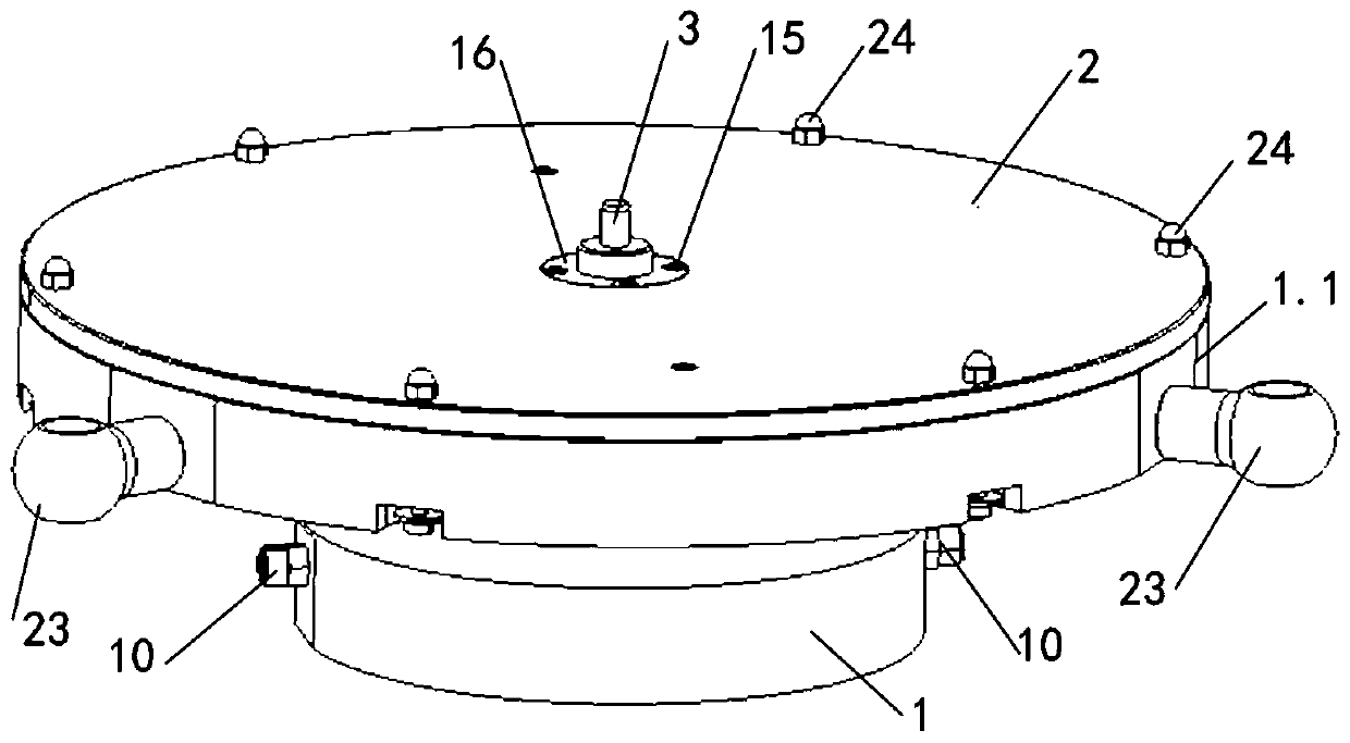
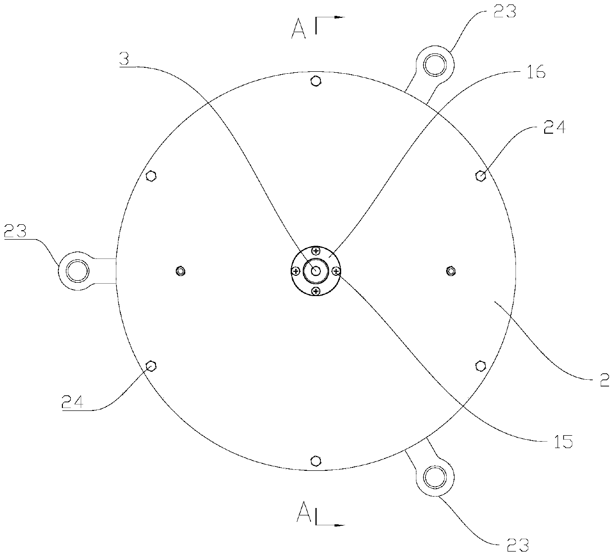
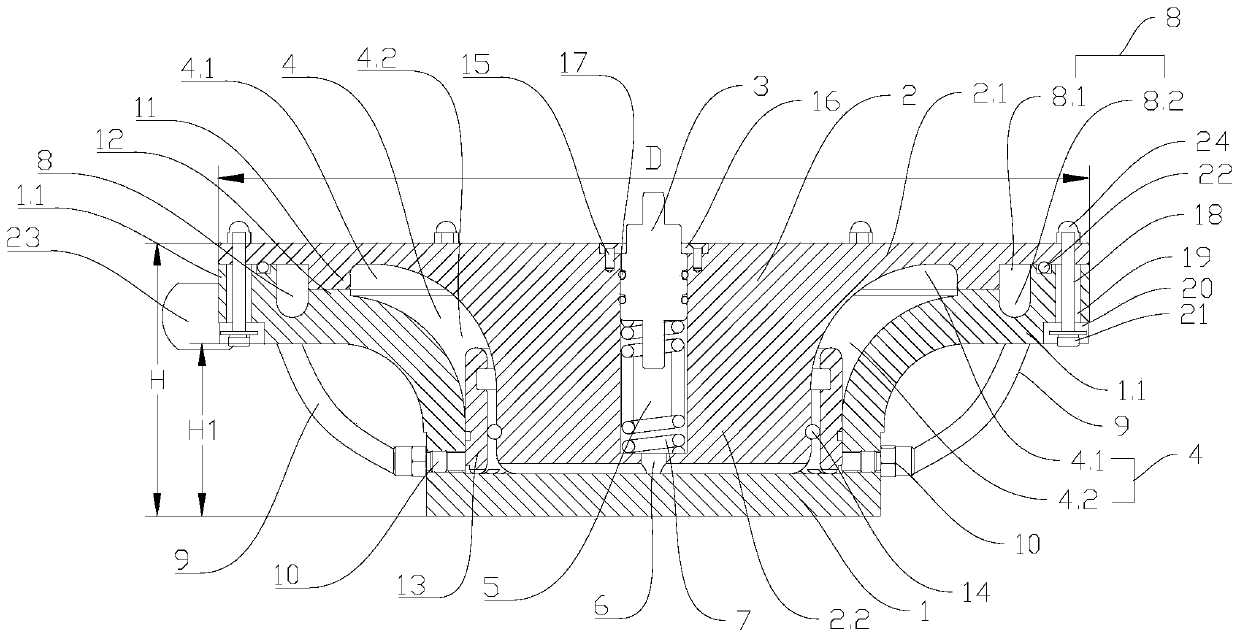
[0034] Such as Figure 1-Figure 3 As shown, this embodiment provides a self-adaptive suspension centering device for mold assembly, including a bearing base 1, a bearing plate 2 and a plunger 3, a hydraulic chamber 4 is provided between the bearing base 1 and the bearing plate 2, and the bearing plate 2 A plunger chamber 5 is provided, and a through hole 6 connecting the plunger chamber 5 and the hydraulic chamber 4 is provided on the carrier plate 2. Specifically, the through hole 6 is arranged at the lower end of the plunger chamber 5, and the plunger 3 and the plunger chamber 5 Sliding fit, the upper end of the plunger chamber 5 on the carrier plate 2 is provided with a limit structure, and a spring 7 is provided between the lower end of the plunger 3 and the plunger chamber 5;

[0035] The carrier plate 2 includes a support plate 2.1 and an extension portion 2.2 extending from the support plate 2.1 toward the carrier seat 1. The support plate 2.1 is connected to the carrie...

Embodiment 2

[0041] This embodiment is optimized and defined on the basis of the above-mentioned embodiment 1.

[0042] A lining ring 13 is arranged inside the hydraulic chamber 4 , the extension part 2.2 is located in the lining ring 13 , and an O-ring 14 is arranged between the extension part 2.2 and the lining ring 13 .

[0043] The lining ring 13 is located in the hydraulic chamber 4, and an O-ring 14 is provided between the lining ring 13 and the extension part 2.2. The O-ring 14 divides the lower part and the upper part of the lining ring 13 into two spaces, and the plunger 3 moves down. The process increases the pressure of the space below the backing ring 13, and squeezes the O-ring 14 under the condition that the pressure in the lower space of the backing ring 13 increases, so that there is a gap between the O-ring 14 and the backing ring 13, and the backing ring The hydraulic oil in the lower space of 13 flows into the upper space of the lining ring 13 from the gap, and then flow...

Embodiment 3

[0046] This embodiment is optimized and defined on the basis of the above-mentioned embodiment 1.

[0047] The limit structure includes a limit ring 16 fixed on the carrier plate 2 by a screw 15, the inner diameter of the limit ring 16 is smaller than the outer diameter of the plunger 3 in the plunger cavity 5, and the plunger 3 stretches out of the plunger cavity 5 The part is slidingly fitted with the limit ring 16.

[0048] Limiting ring 16 is used to limit the moving path of plunger 3, and the upper end that is positioned at plunger chamber 5 is provided with mounting groove on the carrier plate 2, and limit ring 16 is located in the mounting groove, and the upper end surface of limit ring 16 and carrying plate The upper end surface of 2 is flush, and a plurality of screws 15 are evenly provided along the circumferential direction of the axis of the plunger chamber 5, and four screws 15 are provided in this embodiment.


PUM


Abstract

The invention relates to the technical field of die assembly and discloses a self-adaptive suspension centering device for die assembly. The device comprises a bearing base, a bearing plate and a plunger, wherein a hydraulic cavity is arranged between the bearing base and the bearing plate, a plunger cavity is arranged on the bearing plate, a through hole connecting the plunger cavity and the hydraulic cavity is arranged in the bearing plate, the plunger is in sliding fit with the plunger cavity, a limiting structure is arranged on the bearing plate and located at the upper end of the plungercavity, and a spring is arranged between the lower end of the plunger and the plunger cavity; and the bearing plate comprises a support plate and an extension part, the support plate is in floating connection with the bearing base, an oil return cavity and an adjustable sealing structure are further arranged between the bearing base and the bearing plate, and the oil return cavity communicates with the hydraulic cavity through a pipeline. The self-adaptive suspension centering device for die assembly, provided by the invention, solves the problem of difficult centering in a die assembly process. By adopting the structure of the device, the positions of pin holes can be automatically located through the fine adjustment of the position of a lower die, assembly is easily finished, the assembly efficiency of the die is increased, and the assembly precision is improved.

Description

technical field [0001] The invention relates to the technical field of mold assembly, in particular to an adaptive suspension centering device for mold assembly. Background technique [0002] At present, most multi-layer molds are assembled by pin (blind insertion) positioning, so there is always a situation where the upper and lower cavity alignment is difficult during assembly, especially in the assembly of medium and large molds, the upper and lower cavity alignment of medium and large molds is more difficult It is difficult, the adjustment of the mold in the process of mold centering is time-consuming and laborious, the assembly efficiency is low, and the safety in the operation process cannot be guaranteed. Contents of the invention [0003] Aiming at the problems existing in the above-mentioned prior art, the present invention provides a self-adaptive suspension centering device for mold assembly, which solves the problem of difficult centering during the mold assemb...

Claims


Application Information

Patent Timeline
Patent Type & Authority Applications(China)
IPC IPC(8): B23P19/10
CPCB23P19/10
Inventor 黄雯李恒陈平
Owner 绵阳飞腾精密机械科技有限公司
Why Eureka
Try Eureka