A kind of heat exchange equipment and its oil return type condenser

A technology for condensers and oil return tanks, applied in evaporators/condensers, lighting and heating equipment, refrigerators, etc., can solve the problems of difficult structure installation, large space occupation, uneven speed, etc., and achieve simple structure and pipeline , Improve the efficiency of oil return, improve the effect of oil separation efficiency

Active Publication Date: 2017-03-08
GREE ELECTRIC APPLIANCES INC
View PDF8 Cites 0 Cited by
  • Summary
  • Abstract
  • Description
  • Claims
  • Application Information

AI Technical Summary

Problems solved by technology

At present, most units use the oil separator as a separate container and place it in front of the condenser to separate the lubricating oil before entering the refrigeration system. However, this structure has the disadvantages of high production cost, large space occupation, and complicated pipelines.
[0003] In order to overcome the above shortcomings of the external oil separator, the structure of the built-in oil separator is proposed. There are currently two types of built-in oil separators, one is the oil separator built in the compressor, but the oil separator built in the compressor has a complicated structure and installation Difficulties and other shortcomings; so another oil separator built into the condenser was proposed, but the existing structure is difficult to install, the oil separation efficiency is not very high, the pressure drop is relatively large, and the speed of the refrigerant entering the condenser It is also uneven, resulting in a low heat transfer rate of the condenser

Method used


Image

  • A kind of heat exchange equipment and its oil return type condenser
  • A kind of heat exchange equipment and its oil return type condenser
  • A kind of heat exchange equipment and its oil return type condenser

Examples


Embodiment Construction

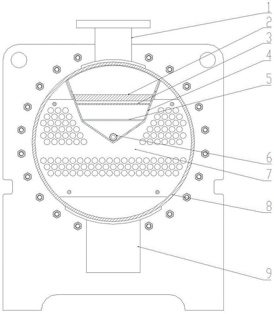
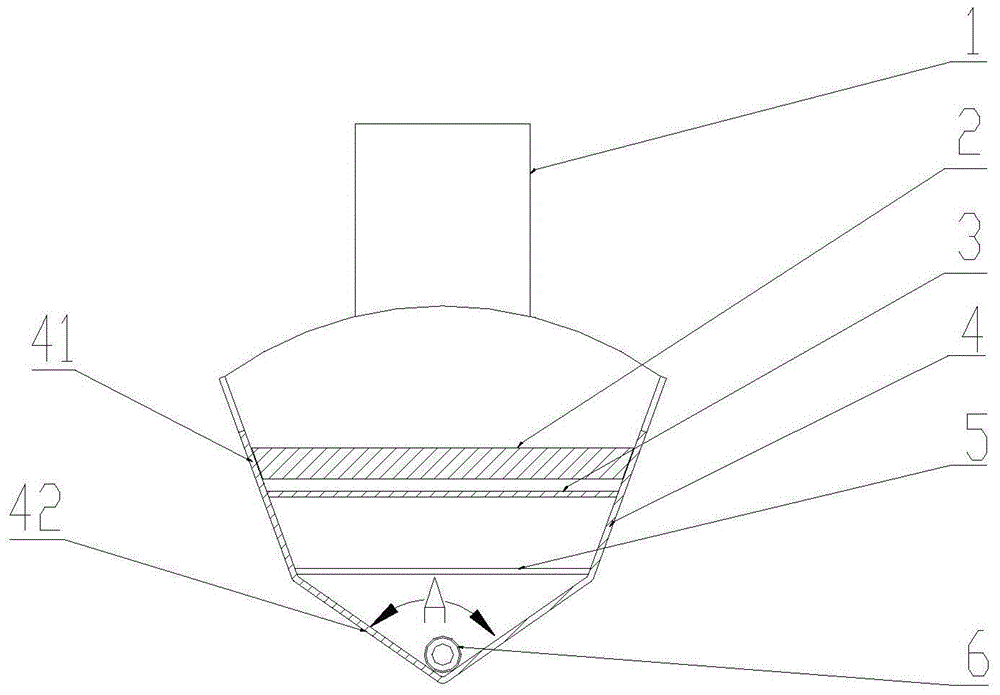
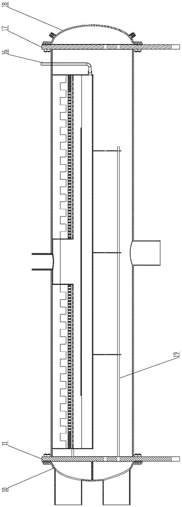
[0027] The invention discloses a heat exchange device and an oil return type condenser thereof. The built-in oil separator has the advantages of simple structure and pipeline, and has high oil separation efficiency, which can effectively improve the heat exchange efficiency of the condenser.

[0028] The following will clearly and completely describe the technical solutions in the embodiments of the present invention with reference to the accompanying drawings in the embodiments of the present invention. Obviously, the described embodiments are only some of the embodiments of the present invention, not all of them. Based on the embodiments of the present invention, all other embodiments obtained by persons of ordinary skill in the art without making creative efforts belong to the protection scope of the present invention.

[0029] see Figure 1-Figure 3 , figure 1 It is a schematic cross-sectional structural diagram of the heat exchange equipment provided by the embodiment of...


PUM


Abstract

The invention discloses an oil return type condenser. An oil separator is arranged in the condenser, and the built-in oil separator has the advantages of being high in oil separation efficiency, simple in structure, simple in pipeline and the like. The built-in oil separator carries out primary separation through a knocking baffle, then carries out secondary separation through a flow equalization board, and finally caries out tertiary separation through a filter screen. The oil separation efficiency is improved through the arrangement, coolants can evenly enter the condenser and make contact with a condenser pipe more evenly through the design of an outlet of the built-in oil separator, and the heat exchanging efficiency of the condenser is improved. The invention further discloses a heat exchanging device with the oil return type condenser.

Description

technical field [0001] The invention relates to the technical field of heat exchange equipment, in particular to a heat exchange equipment and an oil return condenser. Background technique [0002] Since the screw refrigeration compressor sprays a large amount of lubricating oil, the mixture of refrigerant vapor and oil is discharged from the compressor exhaust port. Since the lubricating oil does not evaporate, an oil film will be formed on the wall of the heat exchanger, so that The heat transfer effect and cooling efficiency are greatly reduced. The solution is to add an oil separator before the mixed gas enters the refrigeration system to separate the lubricating oil. At present, most units use the oil separator as a separate container and place it in front of the condenser to separate the lubricating oil before entering the refrigeration system. However, this structure has the disadvantages of high production cost, large space occupation, and complicated pipelines. . ...

Claims


Application Information

Patent Timeline
Patent Type & Authority Patents(China)
IPC IPC(8): F25B39/04F25B43/02
CPCF25B39/04F25B43/02F25B2339/0441
Inventor 杨威胡海利胡东兵王忠哲胡立书陈锦贤
Owner GREE ELECTRIC APPLIANCES INC
Why Eureka
Try Eureka