
Oil separator, compressor, electric appliance and control method of oil separator

An oil separator and compressor technology, applied in the control fields of compressors, oil separators, electrical appliances and oil separators, can solve problems such as poor oil and gas separation capacity and oil storage capacity, improve oil return, and solve shortages. Oil problem, the effect of improving oil and gas separation capacity

Pending Publication Date: 2021-10-01
GREE ELECTRIC APPLIANCES INC
View PDF0 Cites 0 Cited by
  • Summary
  • Abstract
  • Description
  • Claims
  • Application Information

AI Technical Summary

Problems solved by technology

[0005] In order to solve the technical problems of poor oil-gas separation ability and poor oil storage capacity in the structure of the oil separator in the prior art, the application provides a control method for the oil separator, compressor, electrical appliances and oil separator

Method used


Image

  • Oil separator, compressor, electric appliance and control method of oil separator
  • Oil separator, compressor, electric appliance and control method of oil separator
  • Oil separator, compressor, electric appliance and control method of oil separator

Examples


Embodiment Construction

[0035] In order to make the purposes, technical solutions and advantages of the embodiments of the present application clearer, the technical solutions in the embodiments of the present application will be clearly and completely described below in conjunction with the drawings in the embodiments of the present application. Obviously, the described embodiments It is a part of the embodiments of this application, but not all of them. Based on the embodiments in the present application, all other embodiments obtained by persons of ordinary skill in the art without making creative efforts belong to the protection scope of the present application.

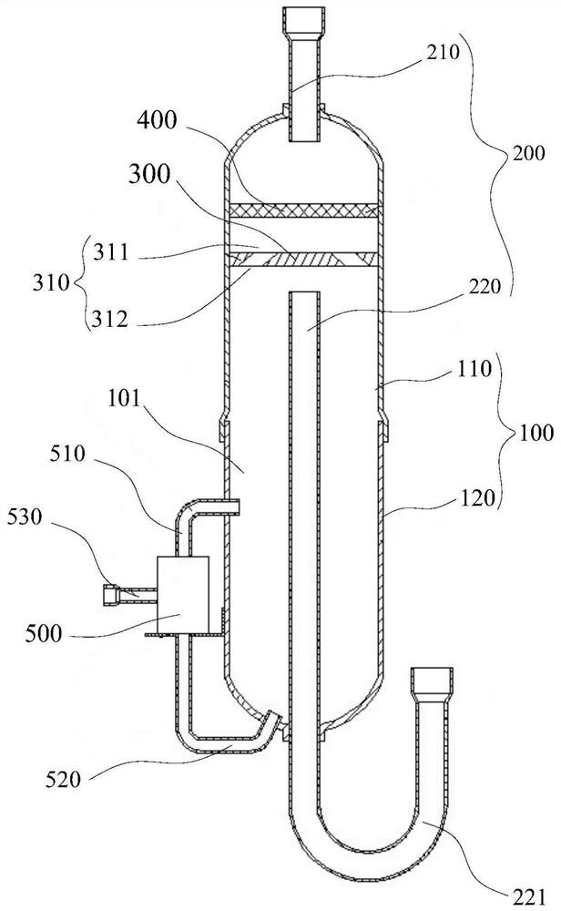
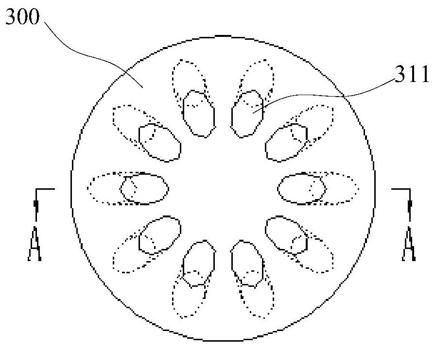
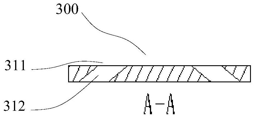
[0036] In order to solve the technical problem that the oil separator of the above-mentioned prior art has weak oil storage capacity, refer to Figure 1-3 . The application provides an oil separator, a heat exchange device, an electrical appliance and a control method for the oil separator. The oil separator separates the oil and gas ...


PUM


Abstract

The invention relates to an oil separator, a heat exchange device, an electric appliance and a control method of the oil separator. The oil separator comprises a shell, an air pipe and a flow guide part. A separation cavity is formed in the shell. The air pipe comprises an air inlet pipe and an air outlet pipe, the inner end of the air inlet pipe communicates with the separation cavity, the outer end of the air inlet pipe communicates with the compressor, the inner end of the air outlet pipe extends into the separation cavity, and an oil storage space is formed in the lower part of the separation cavity. The flow guide part is connected into the shell to separate the separation cavity, the flow guide part is located between the inner end of the air inlet pipe and the inner end of the air outlet pipe, the flow guide part is provided with flow channels, each flow channel comprises a first opening formed in the first surface of the flow guide part and a second opening formed in the second surface of the flow guide part, the distance between the second openings and the inner wall of the shell is smaller than that between the first openings and the inner wall of the shell, and the second openings deviate from the inner end of the air outlet pipe. The flow guide part has the flow guide effect, the proportion of oil entering the air outlet pipe can be greatly reduced, after the oil is discharged from the second opening and condensed, most of the oil is gathered in the oil storage space, the oil-gas separation efficiency can be improved, and the oil shortage problem of the compressor is solved.

Description

technical field [0001] The present application relates to the field of air treatment, in particular to an oil separator, a compressor, an electrical appliance and a control method for the oil separator. Background technique [0002] Air source heat pump air conditioners (hereinafter referred to as heat pump air conditioners) can absorb low-grade energy from the atmospheric environment and convert it into high-grade energy for heating. Pollution is small. Based on the above advantages, heat pump air conditioners are more and more widely used. The compressor is the core component of the heat pump air conditioner. The temperature difference between the temperature of the compressor exhaust pipe or the inlet of the condenser and the saturation temperature corresponding to the actual condensing pressure is called the exhaust superheat. If the compressor has no discharge superheat, the oil discharge rate will be high, causing a large amount of lubricating oil to be discharged fr...

Claims


Application Information

Patent Timeline
Patent Type & Authority Applications(China)
IPC IPC(8): F25B43/02F25B49/02
CPCF25B43/02F25B49/02
Inventor 李志强吕丹丹李健成王萍陈梓杰
Owner GREE ELECTRIC APPLIANCES INC
Learn More