Hub positioning clamp

A technology for positioning fixtures and hubs, applied in manufacturing tools, workpiece clamping devices, etc., can solve problems such as being easily scratched and unable to solve the hub, and achieve the effect of improving the success rate of tire loading, simple structure and accurate positioning

Pending Publication Date: 2019-10-25
皮休车轮科技(台州)有限公司
View PDF2 Cites 2 Cited by
  • Summary
  • Abstract
  • Description
  • Claims
  • Application Information

AI Technical Summary

Problems solved by technology

But this utility model can't solve the problem that the wheel hub is easily scratched

Method used


Image

  • Hub positioning clamp
  • Hub positioning clamp
  • Hub positioning clamp

Examples


Embodiment 1

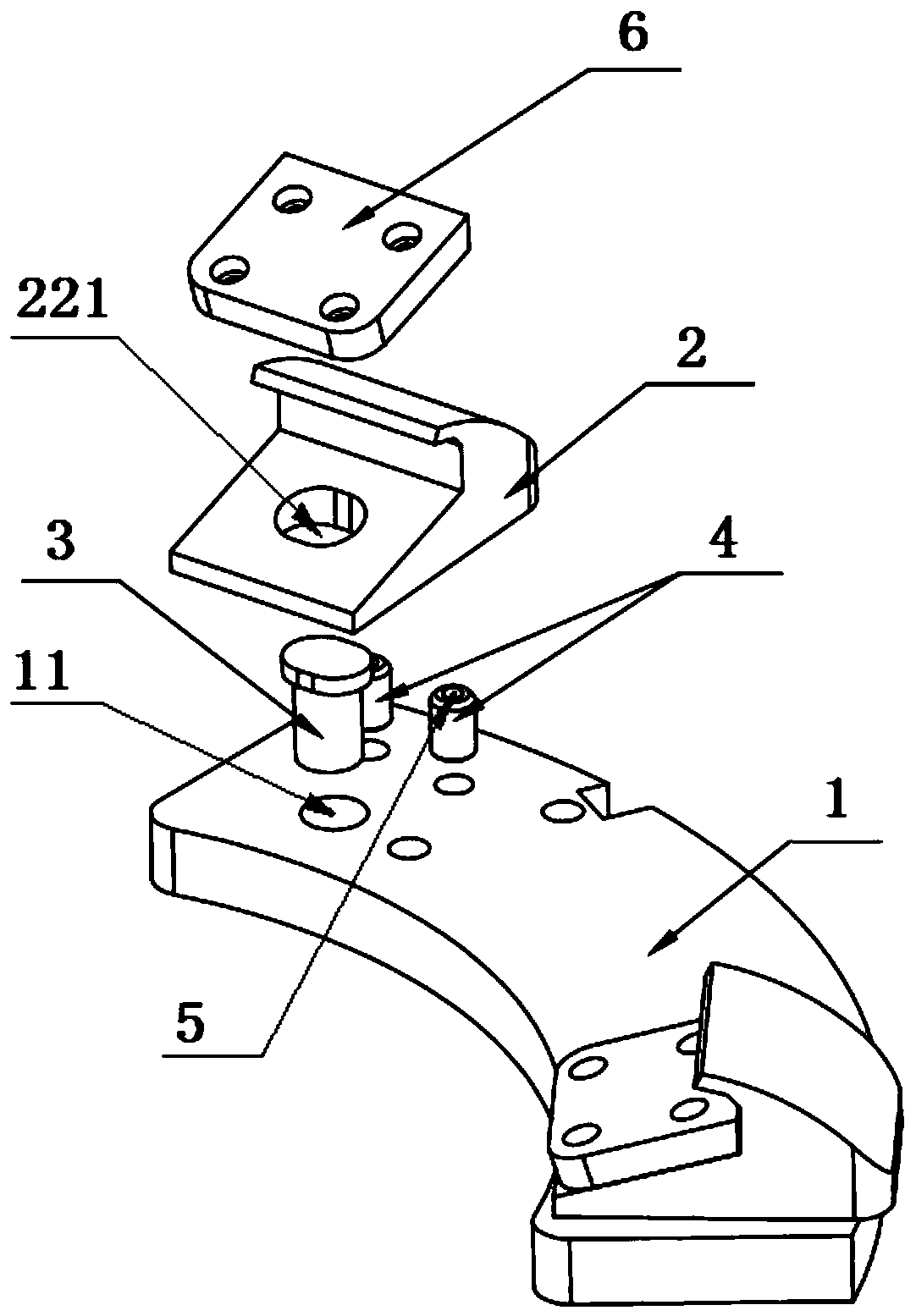
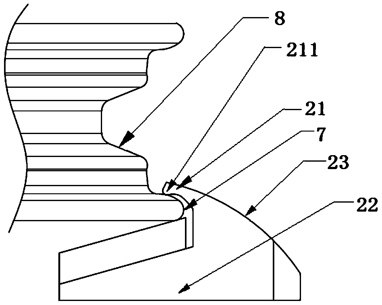
[0032] Such as figure 1 As shown, a hub positioning jig includes a jig base 1 and two jig jaws 2 installed at both ends of the jig base 1. The jig jaw 2 includes a support end 22, a jaw tail 23 connected to the support end 22, and a jaw that is connected to the clamp. The clamping end 21 connected to the claw tail 23 is provided with an arc-shaped protrusion 211 on the top of the clamping end 21, a first hole 221 is provided on the supporting end 22, and a second hole 11 is respectively provided at both ends of the clamp base 1. , the first pin 3 passes through the first hole 221 and the second hole 11 to install the clamp claw 2 on the clamp base 1 , and the clamp claw 2 rotates on the clamp base 1 with the first pin 3 as the axis.

[0033] Two second pins 4 are arranged on the outside of the first pin 3, and a ball 5 is arranged on the top of the second pin 4. touch. The second pin 4 is used for assisting the universal rotation of the clamp claw 2 on the clamp base 1. Due ...

Embodiment 2

[0040] The difference between this embodiment and Embodiment 1 is that the positioning of a hub is jointly completed by three hub positioning jigs. The above three hub positioning fixtures are evenly engaged on the hub, and the angle between any two adjacent hub positioning fixtures is 120°.

Embodiment 3

[0042] The difference between this embodiment and Embodiment 1 is that the positioning of a hub is jointly completed by four hub positioning jigs. The above four hub positioning fixtures are evenly engaged on the hub, and the angle between any two adjacent hub positioning fixtures is 90°.


PUM


Abstract

The invention discloses a hub positioning clamp. The hub positioning clamp comprises a clamp base (1) and two clamp claws (2) installed at the two ends of the clamp base (1); and the clamp claws (2) comprise supporting ends (22), claw tail parts (23) and clamping ends (21), wherein arc-shaped bulges (211) are arranged at the top ends of the clamping ends (21), the supporting ends (22) are providedwith first holes (221), the two ends of the clamp base (1) are correspondingly provided with second holes (11), first pins (3) penetrate through the first holes (221) and the second holes (11) to beused for installing the clamp claws (2) on the clamp base (1), and the clamp claws (2) can rotate on the clamp base (1) by taking the first pins (3) as axes. According to the hub positioning clamp, the slot-shaped positioning method is adopted, and the clamp claws can rotate in all directions, so that the clamp is suitable for hubs with different sizes, and no influence is generated on a tire assembling process; and in addition, the structure of the clamp is further improved so that the hub cannot be scratched.

Description

technical field [0001] The invention relates to the technical field of automatic tooling fixtures, in particular to a hub positioning fixture. Background technique [0002] In the existing tire assembly process, the mode of fixing the wheel hub by the clamp and then loading the tire is generally adopted. At present, the common wheel clamps on the market generally adopt the cross positioning, but in the process of fixing the wheel hub, it is easy to scratch the wheel hub. For alloy wheels, once the gold-plated layer on the outer surface is scratched, the life and stability of the wheel will be affected. In addition, the existing wheel clamp has a single function and cannot be used for clamping wheels of different sizes, and the clamping will affect the assembly of the tire, which will easily lead to failure of tire assembly. [0003] The utility model patent with the authorized notification number CN207616441U discloses a wheel hub clamping device, which includes a clamp bo...

Claims


Application Information

Patent Timeline
Patent Type & Authority Applications(China)
IPC IPC(8): B25B11/02
CPCB25B11/02
Inventor 谢长河
Owner 皮休车轮科技(台州)有限公司
Why Eureka
Try Eureka