Eureka AIR delivers breakthrough ideas for toughest innovation challenges, trusted by R&D personnel around the world.

Glass placement rack

A technology for placing racks and glass, which is applied in the direction of transportation, packaging, and load hanging components, etc. It can solve the problems of safety hazards, falling, easy shaking, etc., and achieve the effect of safe use and avoiding glass falling

Inactive Publication Date: 2017-05-24
北京四汇建筑工程有限责任公司
View PDF9 Cites 3 Cited by
  • Summary
  • Abstract
  • Description
  • Claims
  • Application Information

AI Technical Summary

Problems solved by technology

[0004] This kind of glass rack has a simple structure, but there is still a problem in actual use. When installing glass, the lower floors are manually transported glass, while the upper floors are transported by electric hoists or tower cranes. Electric hoist or tower cranes The glass rack and the glass are hoisted together with the steel wire rope and transported to the designated floor. When the glass rack is transported to the air, it will be blown by the wind. At the same time, the mechanical lifting force of the electric hoist or tower crane is not stable enough, and the steel wire rope is relatively soft. This reason causes the glass rack to shake easily when it is in the air, and once the inclination angle is too large, the glass will turn with its lower edge as the rotating shaft in the direction away from the vertical bar, and then fall from the glass rack, so there is a certain degree of safety. Hidden danger

Method used


Image

  • Glass placement rack
  • Glass placement rack
  • Glass placement rack

Examples


Embodiment 1

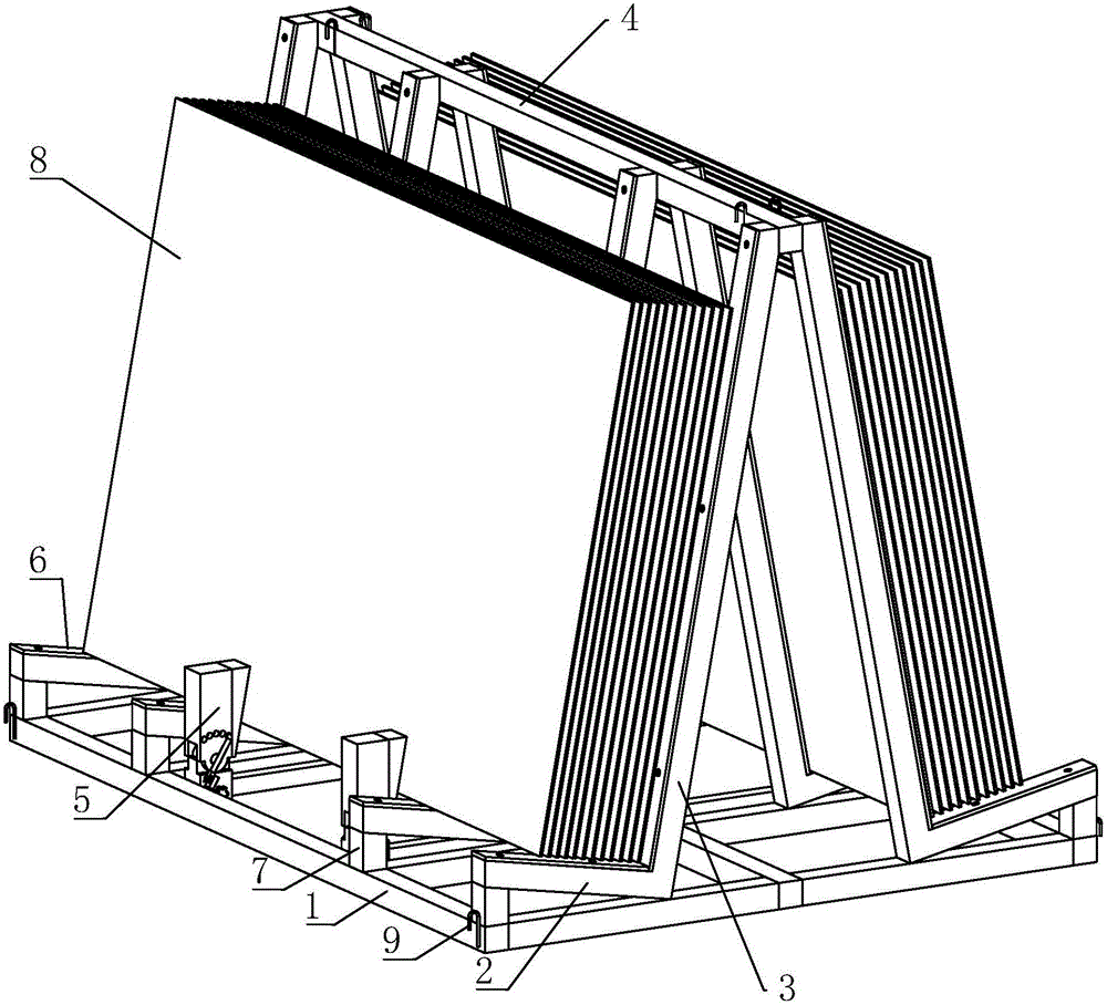
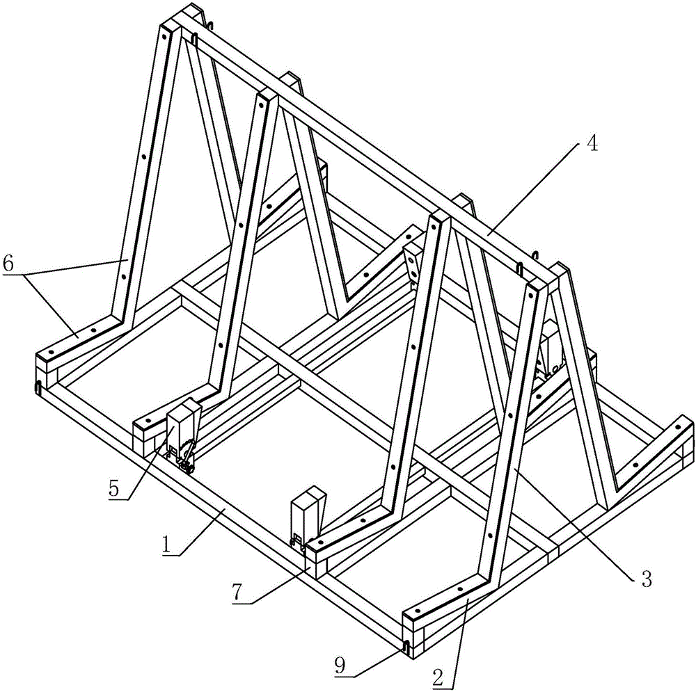
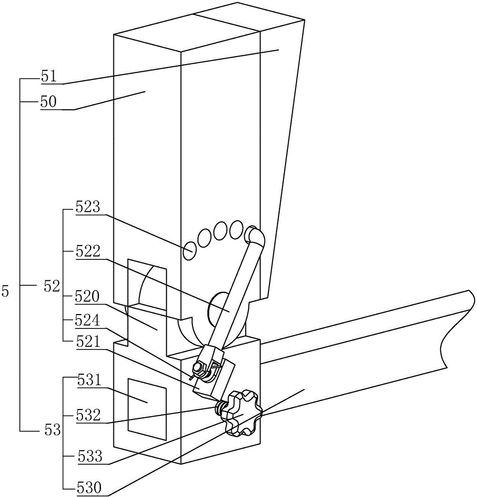
[0032] Embodiment 1: A kind of glass placement rack, refer to figure 1 , figure 2 , comprising a rectangular underframe 1 set on the ground, which is welded using square steel pipes. Four corners of the underframe 1 are respectively provided with a suspension hook 9 for lifting. On one side of the chassis 1 along its length direction, there are four support rods 2 with one end upturned at intervals. One end is directly welded to the chassis 1. On the lower end of the support rod 2, a relying rod 3 is also connected, and the relying rod 3 is inclined to the side away from the supporting rod 2 and has an angle of 90°-100° with the supporting rod 2. Rely on the upper end of the bar 3 to be connected by a crosspiece 4, and the crosspiece 4 is made of a square steel pipe and welded with the rely on the bar 3. If want to further improve the intensity of glass placement rack, also can set several crosspieces 4 more.

[0033] refer to figure 1 , figure 2 , in order to increas...


PUM


Abstract

The invention discloses a glass placement rack. According to the technical scheme essential points, the glass placement rack comprises a bottom frame, at least two supporting rods, leaning rods and a cross rail, the supporting rods are arranged on the bottom frame in a spaced mode, one end of each supporting rod is warped upwards, the lower ends of the leaning rods are connected to the lower ends of the supporting rods and inclined in the direction away from the supporting rods, the cross rail is arranged on the upper ends of the leaning rods and fixedly connected with the leaning rods in sequence, an included angle at 90-100 degrees exists between the supporting rods and the leaning rods, the side, away from the leaning rods, of the bottom frame is provided with a plurality of extrusion mechanisms at intervals, and the inclination angle of the face, facing the leaning rods, of the extrusion mechanisms is the same as that of the leaning rods. The problems that an existing glass placement rack is likely to swing when hoisted in air, and glass is likely to fall down once the inclination angle is too large are solved.

Description

technical field [0001] The invention relates to glass, in particular to a glass placement rack. Background technique [0002] In the housing construction project, after the building frame is built, the glass needs to be installed. The glass is transported to the construction site by a transport vehicle, and is pre-stored on the glass shelf after unloading. [0003] Authorized announcement number is that the Chinese invention patent of CN204280348U discloses a kind of glass placement rack. The glass placing rack includes a top rod, a first basic rod, a second basic rod, a vertical rod, a supporting rod and a connecting rod, and an included angle of 90°-100° exists between the vertical rod and the connecting rod. When in use, the lower edge of the glass rests on the connecting rod, while the upper edge of the glass rests on the vertical rod, the glass tilts toward the vertical rod or fits on the vertical rod, and multiple pieces of glass are stored at the same inclination ang...

Claims


Application Information

Patent Timeline
IPC IPC(8): B66C1/10
CPCB66C1/10
Inventor 吴广礼杨邵宾朱帝
Owner 北京四汇建筑工程有限责任公司
Why Eureka
Eureka Blog
Learn More