Cutting device for wood processing
A cutting device and wood technology, applied in the field of wood processing, can solve the problems of reduced cutting efficiency, workshop pollution, short service life of the cutting wheel, etc., and achieve the effects of efficient cutting processing, cooling and dust generation, and prevention of dust generation.
- Summary
- Abstract
- Description
- Claims
- Application Information
AI Technical Summary
Problems solved by technology
Method used
Image
Examples
Embodiment 1
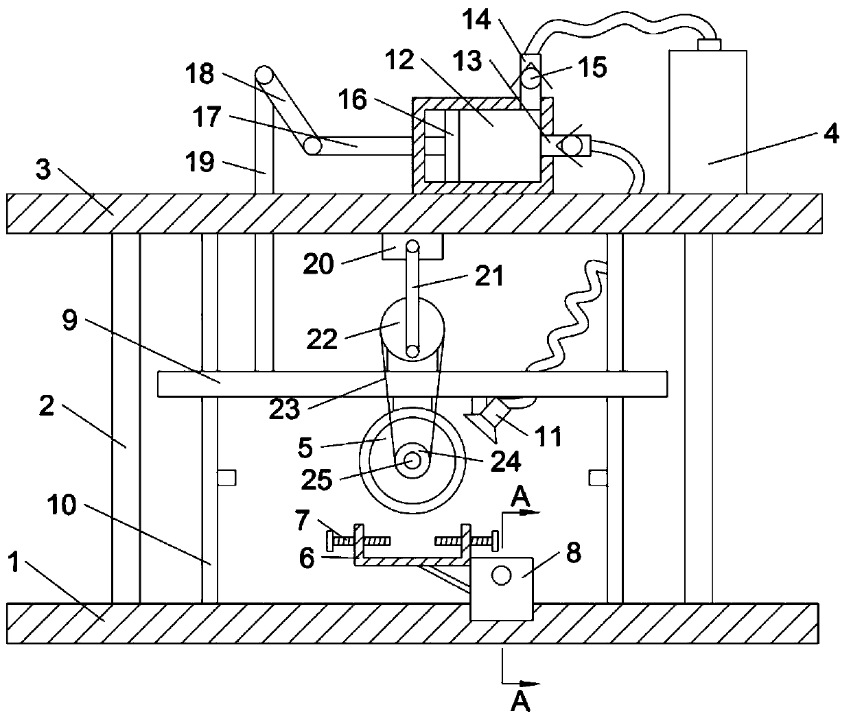
[0026] Please refer to the attached Figure 1-3 , this embodiment provides a cutting device for wood processing, which includes a top board 3 and a cutting assembly, the top board 3 is fixedly installed above the base 1 through several sets of pillars 2 . In addition, several groups of guide rods 10 are fixed on the bottom of the top plate 3, and the guide rods 10 are covered with lifting plates 9, and the lifting plates 9 and the guide rods 10 are slidably matched, and are located between the base 1 and the top plate 3. between.
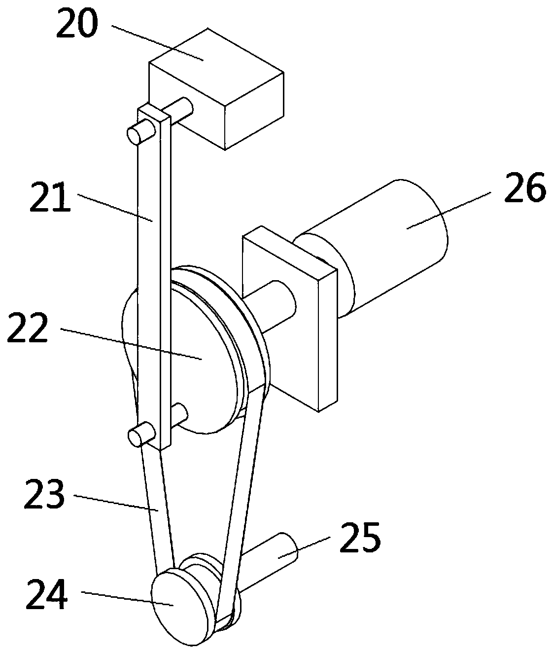
[0027] Further, the cutting assembly is arranged on the bottom of the lifting plate 9, and the lifting plate 9 is provided with a driving mechanism and a reciprocating assembly, and one side of the cutting assembly is provided with a spray head 11, and the spray head 11 is connected with the infusion chamber. 12 is connected, and the infusion chamber 12 is provided with an infusion assembly for delivering water to the nozzle 11; the drive mechanism...
Embodiment 2
[0039] Please refer to the attached Figure 4 , in order to facilitate the recycling of the water sprayed by the nozzle 11, this embodiment is improved on the basis of embodiment 1. Specifically, the base 1 is also equipped with a sump 31, and the sump 31 It communicates with the liquid discharge pipe 32 , and the liquid discharge pipe 32 is provided with a filter screen 33 , and the liquid discharge pipe 32 is also connected with the liquid storage tank 4 through a liquid suction pump 34 . In addition, the bottom of the placement frame 6 is also provided with several groups of liquid holes 35, and the liquid collection tank 31 is located directly below the spray head 11 and the placement frame 6; through the setting of the liquid collection tank 31, the spray head 11 can be sprayed Through the setting of the filter screen 33 and the suction pump 34, the water recovered in the sump 31 can be filtered, and circulated to the liquid storage tank 4 for use.
Embodiment 1-2
[0040] In conjunction with Embodiment 1-2, the cutting device provided by the embodiment of the present invention, when in use, first place the long strip of wood on the placement frame 6, and tighten the clamping screw 7 to clamp and fix the wood; then , start the first motor 26, you can simultaneously drive the cutting wheel 5 to move downward and drive the cutting wheel 5 to rotate, so that the wood can be efficiently cut; in addition, by starting the first motor 26, the liquid storage tank can also be turned The water in 4 is transported in the shower head 11 to carry out sprinkling operation.
[0041] In summary, in the embodiment of the present invention, a reciprocating assembly with a driving wheel 22 and a second movable rod 21 is provided on the slidable lifting plate 9, and a rotatable cutting wheel 5 is set at the bottom of the lifting plate 9, and the The cutting wheel 5 is connected to the driving mechanism through the first transmission assembly with the transmi...
PUM
 Abstract
Description
Claims
Application Information
 - R&D
- Intellectual Property
- Life Sciences
- Materials
- Tech Scout
- Unparalleled Data Quality
- Higher Quality Content
- 60% Fewer Hallucinations
Browse by: Latest US Patents, China's latest patents, Technical Efficacy Thesaurus, Application Domain, Technology Topic, Popular Technical Reports.
© 2025 PatSnap. All rights reserved.Legal|Privacy policy|Modern Slavery Act Transparency Statement|Sitemap|About US| Contact US: help@patsnap.com


