
Mounting and cutting process for shaped raw stone, angle-adjustable special charging platform and cutting machine

A cutting machine and stone technology, applied in the direction of stone processing tools, stone processing equipment, work accessories, etc., can solve the problems of low efficiency, a lot of waste, and the inability to unify one machine for dual use, etc.

Active Publication Date: 2021-07-30
保文明 +1
View PDF15 Cites 0 Cited by
  • Summary
  • Abstract
  • Description
  • Claims
  • Application Information

AI Technical Summary

Problems solved by technology

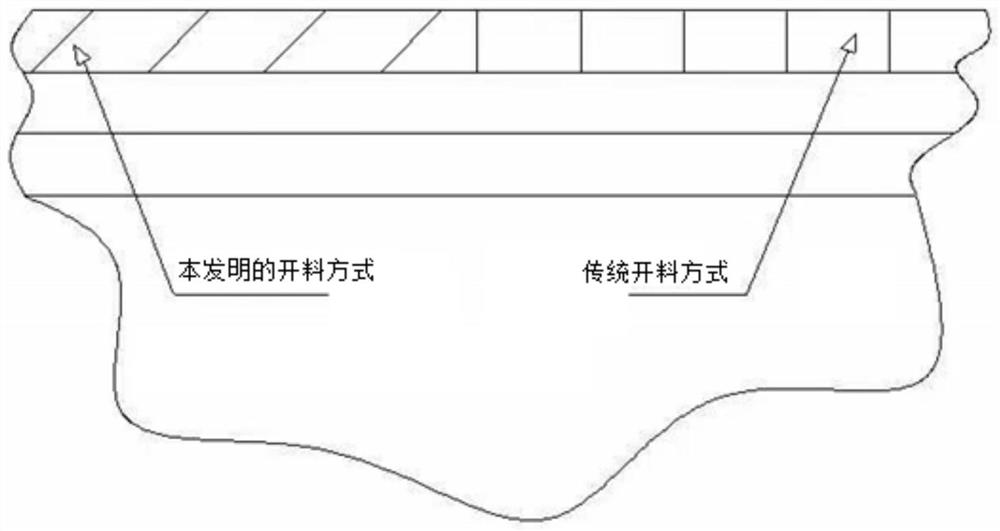
[0005] (1) When the current blocks are shipped from the mine, they are all cut into cube-shaped stones for discharge. When cutting corner stones with this conventional and traditional shape, there will be more waste. and the bottom will cause greater waste
[0006] (2) The current corner stone cutting equipment is too specialized and can only be used to cut corner stone. When cutting traditional flat stone, it needs to be switched to traditional stone cutting equipment, that is, the equipment has poor compatibility and cannot be unified. Dual use in one machine
When cutting a corner stone with unequal thickness on both sides, it is usually necessary to alternate the direction of the thick side on a stone to complete the cutting of a stone. It is necessary to repeatedly change the angle and direction of the cutting tool, etc., which is time-consuming and laborious, and the efficiency is low.

Method used


Image

  • Mounting and cutting process for shaped raw stone, angle-adjustable special charging platform and cutting machine
  • Mounting and cutting process for shaped raw stone, angle-adjustable special charging platform and cutting machine
  • Mounting and cutting process for shaped raw stone, angle-adjustable special charging platform and cutting machine

Examples


Embodiment 1

[0045] Embodiment 1: a kind of loading and cutting process of shaped raw stone 7, as Figure 1-5 as shown,

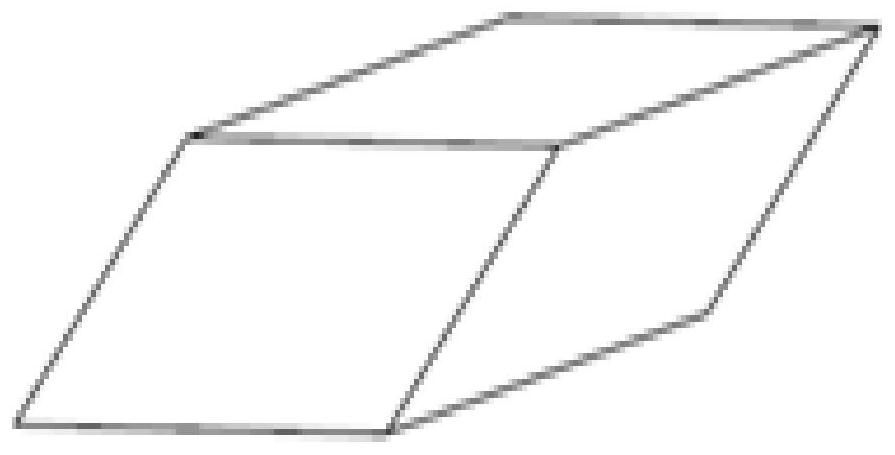
[0046] Step S1, cutting diagonally along the length direction from the block to obtain several pieces of shaped raw stone 7 in the shape of a rhombus or a parallelogram;

[0047] Step S2, connecting the inclined bottom surface of the lower end of the shaped raw stone 7 with one or more pieces of auxiliary materials to form a whole, and then installing them on the material platform to cut the stone materials. During cutting, the shaped raw stone 7 is placed obliquely, so that the inclined plane to be cut at the beginning is maintained vertically, and then the cutting can be started. Such shaped raw stone 7 is used for corner stone cutting, and the waste is controlled at a minimum. The material body is inclined, and the two ends form a vertical plane, that is, the inclined plane is used as the plane of the cut corner stone, thereby greatly reducing the remaining waste ma...

Embodiment 2

[0050] Embodiment 2: special material platform, such as Figure 6 —8,

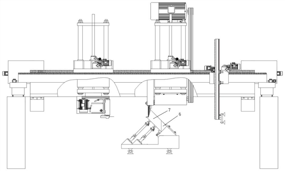
[0051] A material platform with adjustable stone angle is located directly below the bridge cutting machine, and the stone material is installed on the material platform. The material platform can adjust the inclination angle of the installed stone material and fix it at the adjusted angle for stone material cutting; the horizontal The cutting assembly 2 can adjust the included angle between the horizontal cutting tool and the horizontal plane. The obliquely placed stones are monolithic diamond-shaped or parallelogram-shaped raw stones whose bottom is connected with auxiliary materials; specifically: the stone angle-variable material table 1 includes: table top 11, stone support rotating seat set at the front end of the table 12. The bottom of the stone is installed on the stone support rotating seat, and the other end of the table is installed with one or more rows of telescopic roof devices installed al...

Embodiment 3

[0052] Embodiment 3: Bridge-type shifting and cutting, flat stone dual-purpose cutting device, such as Figure 6 —16,

[0053] A cutting machine for shaped raw stone, on the main beam 10 is installed a pair of vertical cutting assembly 3 and horizontal cutting assembly 2 that can be relatively independently moved horizontally and vertically, the main shaft end of the vertical cutting assembly 3 can be A replaceable vertical cutting assembly is installed in the way of disassembly, and the vertical cutting assembly is one of the cornerstone cutting assembly and the flat stone cutting assembly, each of which includes several flanges 103, partitions 105 and several pieces of size Different cutterheads 104, the cutterheads 104 are respectively installed and set on the end of the main shaft through a pair of flanges 103 and a partition 105; the material table is installed on the ground below the cutting machine in a removable manner; The platform can adjust the inclination angle of...


PUM


Abstract

The invention discloses a process for raw stone shaping, auxiliary stone adhesion supplementation, charging platform angle adjustment and mounting and cutting. The bottom of shaped raw stone is in the shape of parallelogram and rhombus during mine blanking, the shaped stone is mounted, auxiliary stone is mounted in an adhesion supplementing mode, according to the numerous characteristics that the charging platform mounting angle is adjustable, a horizontal cutting assembly and a vertical cutting assembly have horizontal lifting and transverse moving functions, and meanwhile the angle of a horizontal cutter shaft shell mounting seat is adjustable, integrated corner stone with the same specification and different thicknesses on two sides can be sequentially cut from top to bottom in the same direction by using large and small combined tools for vertical cutting and a single-knife horizontal cutting tool, and due to the fact that the angle of the horizontal cutter shaft shell mounting seat is adjustable, corner stone with various included angles can be cut; the pain points that raw materials are wasted in traditional corner stone cutting, and a part of the materials need to be modeled, pasted and thickened are solved; and a cutterhead flange partition plate of the vertical cutting assembly and a corresponding traditional charging platform are replaced, traditional flat stone can be cut, and the process has the advantages of high production efficiency and good quality.

Description

technical field [0001] The present invention and the technical field of stone cutting equipment mainly relate to raw stone and its specific shape after cutting, cutting technology, equipment and devices, specifically the cutting technology of shaped raw stone, a special material platform with adjustable angle and a cutting machine. Background technique [0002] Cutting machine is a very mature processing machine, which is widely used to cut materials. The most common is stone cutting machine, which is usually used to cut large stone wool into plates of required thickness. In actual stone construction applications, profiles with corners are often required, such as steps, door pockets, corner lines of window pockets, corners of decorative walls, baseboards, bar counters, washstands, large curbstones, etc. Since the existing stone cutting machine cannot directly process corner profiles, it is labor-intensive, time-consuming, and wasteful. Therefore, when it is necessary to use ...

Claims


Application Information

Patent Timeline
IPC IPC(8): B28D1/24B28D7/04
CPCB28D1/24B28D7/04Y02P40/57
Inventor 保文明王桀
Owner 保文明
Learn More