
Clutch mechanism for imprinting device of printing machine

A clutch mechanism and printing machine technology, applied in printing machines, rotary printing machines, printing, etc., can solve the problems of processing influence, film effective length change, waste generation, etc., and achieve the effect of avoiding waste and avoiding influence

Inactive Publication Date: 2019-10-25
安徽文博纸品印刷有限公司
View PDF18 Cites 1 Cited by
  • Summary
  • Abstract
  • Description
  • Claims
  • Application Information

AI Technical Summary

Problems solved by technology

[0003] The technical problem to be solved by the present invention is that in the working process of the printing machine, the process of printing is completed through the mutual cooperation of the plate roller and the embossing roller; , If the distance is too large, the effective length of the film will change, which will affect the processing and produce waste at the same time. A clutch mechanism for the embossing device of the printing press is provided to solve the above problems

Method used


Image

  • Clutch mechanism for imprinting device of printing machine
  • Clutch mechanism for imprinting device of printing machine
  • Clutch mechanism for imprinting device of printing machine

Examples


Embodiment

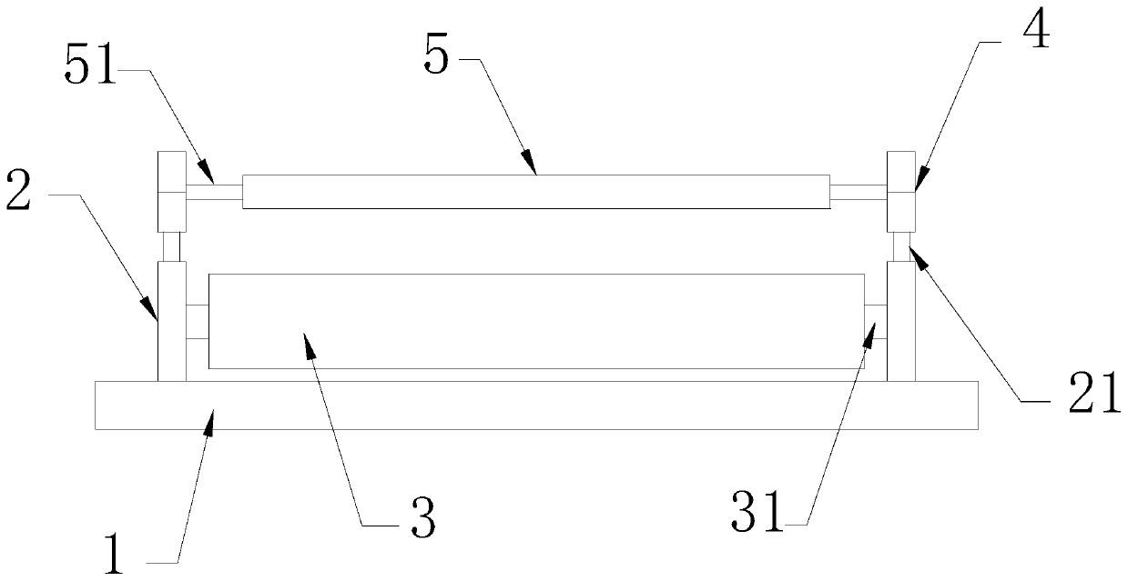
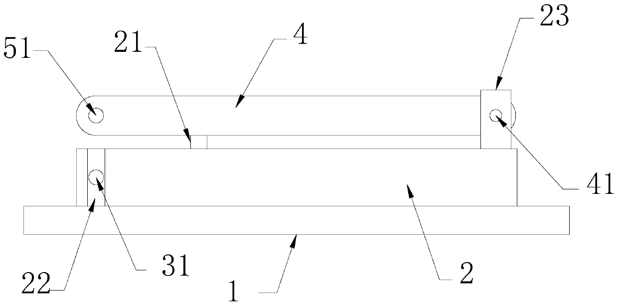
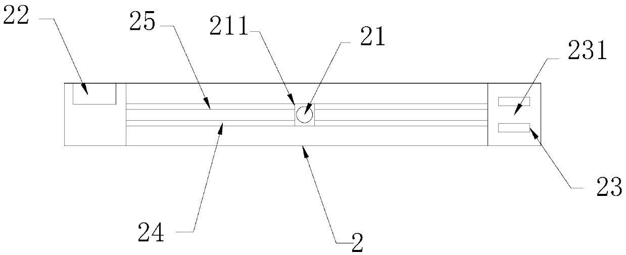
[0026] Example: such as Figure 1-6 As shown, the present invention provides a clutch mechanism of an embossing device of a printing machine, including a working base plate 1, a plate roller fixing bracket 2, a plate roller 3, an embossing roller fixing bracket 4, an embossing roller 5 and a controller. The roller fixing bracket 2 and the embossing roller fixing bracket 4 are all arranged in pairs, and are respectively arranged on both sides of the plate roller 3 and the embossing roller 5; 2. The whole is in the shape of a long strip. There are first rotating shafts 31 arranged on both sides of the printing roller 3. The printing roller 3 is installed on one end of the printing roller fixing bracket 2 through the first rotating shaft 31. The embossing roller fixing bracket 4 is installed on the printing roller fixing bracket 2. The other end of the bracket 2; the embossing roller fixing bracket 4 has the same length as the version roller fixing bracket 2, and the two ends of ...


PUM


Abstract

The invention discloses a clutch mechanism for an imprinting device of a printing machine. The clutch mechanism comprises a working base plate, plate roller fixing supports, a plate roller, impressingroller fixing bracket, an impressing roller and a controller; both the plate roller fixing supports and the impressing roller fixing supports are arranged in pairs and are arranged on the two sides of the plate roller and the impressing roller correspondingly; the plate roller fixing supports are fixedly arranged on the working base plate and are integrally of strip-shaped plate-like structures;first rotating shafts are arranged on the two sides of the plate roller; the plate roller are arranged at one ends of the plate roller fixing supports through the first rotating shafts; the impressingroller fixing supports are arranged at the other ends of the plate roller fixing supports and are the same as the plate roller fixing supports in length; driving shafts are arranged at the two ends of the impressing roller, and the impressing roller is arranged on the impressing roller fixing supports through the driving shafts; the driving shafts are provided with driving motors; and the drivingmotors are connected to the controller. According to the clutch mechanism, each of the plate roller and the impressing roller is provided with the supports, the clutch between the rollers is realizedby controlling the supports, and the relative position is controlled.

Description

technical field [0001] The invention relates to the technical field of printing machinery, in particular to a clutch mechanism of an embossing device of a printing machine. Background technique [0002] During the working process of the printing machine, the printing process is completed through the mutual cooperation of the plate roller and the embossing roller; in the process of processing, in the process of adjusting the machine, it is necessary to separate the plate roller and the embossing roller by a distance at one end. If the distance is too large, the effective length of the film will be caused. Variations, which affect processing and generate waste. Contents of the invention [0003] The technical problem to be solved by the present invention is that in the working process of the printing machine, the process of printing is completed through the mutual cooperation of the plate roller and the embossing roller; , If the distance is too large, the effective length ...

Claims


Application Information

Patent Timeline
Patent Type & Authority Applications(China)
IPC IPC(8): B41F13/20B41F13/34
CPCB41F13/20B41F13/34
Inventor 李晓梅
Owner 安徽文博纸品印刷有限公司
Learn More