Battery-replacement moving and carrying device capable of achieving floating without lateral force

A transfer device and lateral force technology, applied in the direction of power devices, electric power devices, charging stations, etc., can solve problems such as poor mobility, high infrastructure requirements, and limited space at the bottom of the vehicle, so as to reduce the vertical size and facilitate promotion Application, meet the effect of fast battery replacement

Pending Publication Date: 2019-10-25
BOZHON PRECISION IND TECH CO LTD
View PDF0 Cites 6 Cited by
  • Summary
  • Abstract
  • Description
  • Claims
  • Application Information

AI Technical Summary

Problems solved by technology

[0003] Although a variety of battery replacement methods have emerged, such as using a mobile battery replacement car to transport batteries to automatically replace battery components, during the battery replacement process, due to the limited space at the bottom of the vehicle, the battery replacement car cannot easily enter and exit the bottom of the vehicle after carrying the battery components. If the buried track is adopted, the overall infrastructure requirements of the power exchange station are high, the construction project takes a long time, and the maneuverability is poor; if the vehicle is lifted, the lifting mechanism is required to be high, and the lifting space is relatively large, which affects the overall power exchange. The safety control of the process is difficult and consumes a lot of energy
[0004] On the other hand, in the process of battery replacement, the battery pack at the bottom needs to be replaced accurately, and the position of the vehicle or mobile battery replacement car needs to be adjusted, but when positioning and adjusting the vehicle or mobile battery replacement car , there will inevitably be errors. In order to make the positioning and alignment actions go smoothly, the target object needs to be able to float freely, that is, the contact surface between the mobile battery replacement car and the battery pack and the support surface that is in contact with the vehicle need to be floating, but the existing The mobile battery replacement trolley can only meet the small fluctuations in the upper and lower ranges, and at the same time cannot adjust the position in the horizontal plane, making it difficult to carry out the battery replacement process accurately and efficiently; but it is easy to happen during the floating process in the horizontal direction. Deviation from the middle position produces a lateral force back to the center, making the battery replacement process unstable, resulting in unnecessary bumps when installing and disassembling, and affecting battery life

Method used


Image

  • Battery-replacement moving and carrying device capable of achieving floating without lateral force
  • Battery-replacement moving and carrying device capable of achieving floating without lateral force
  • Battery-replacement moving and carrying device capable of achieving floating without lateral force

Examples


Embodiment 1

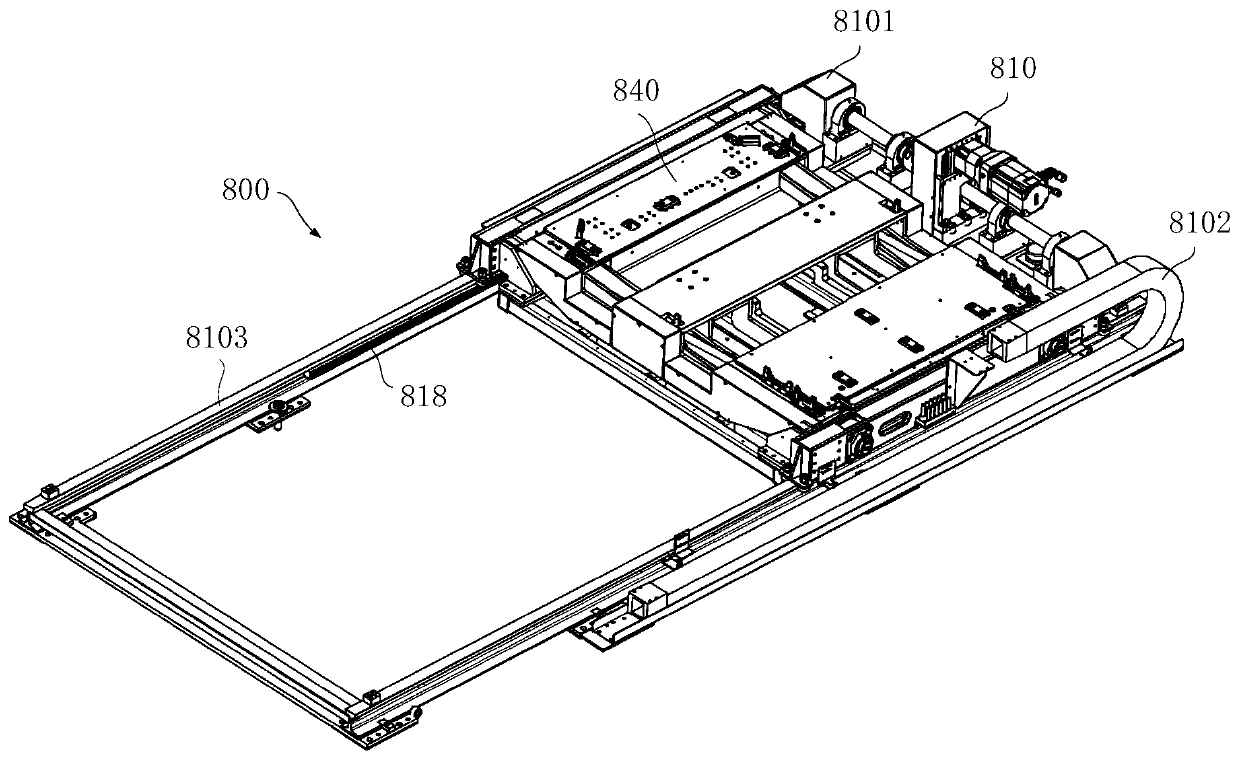
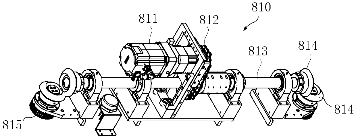
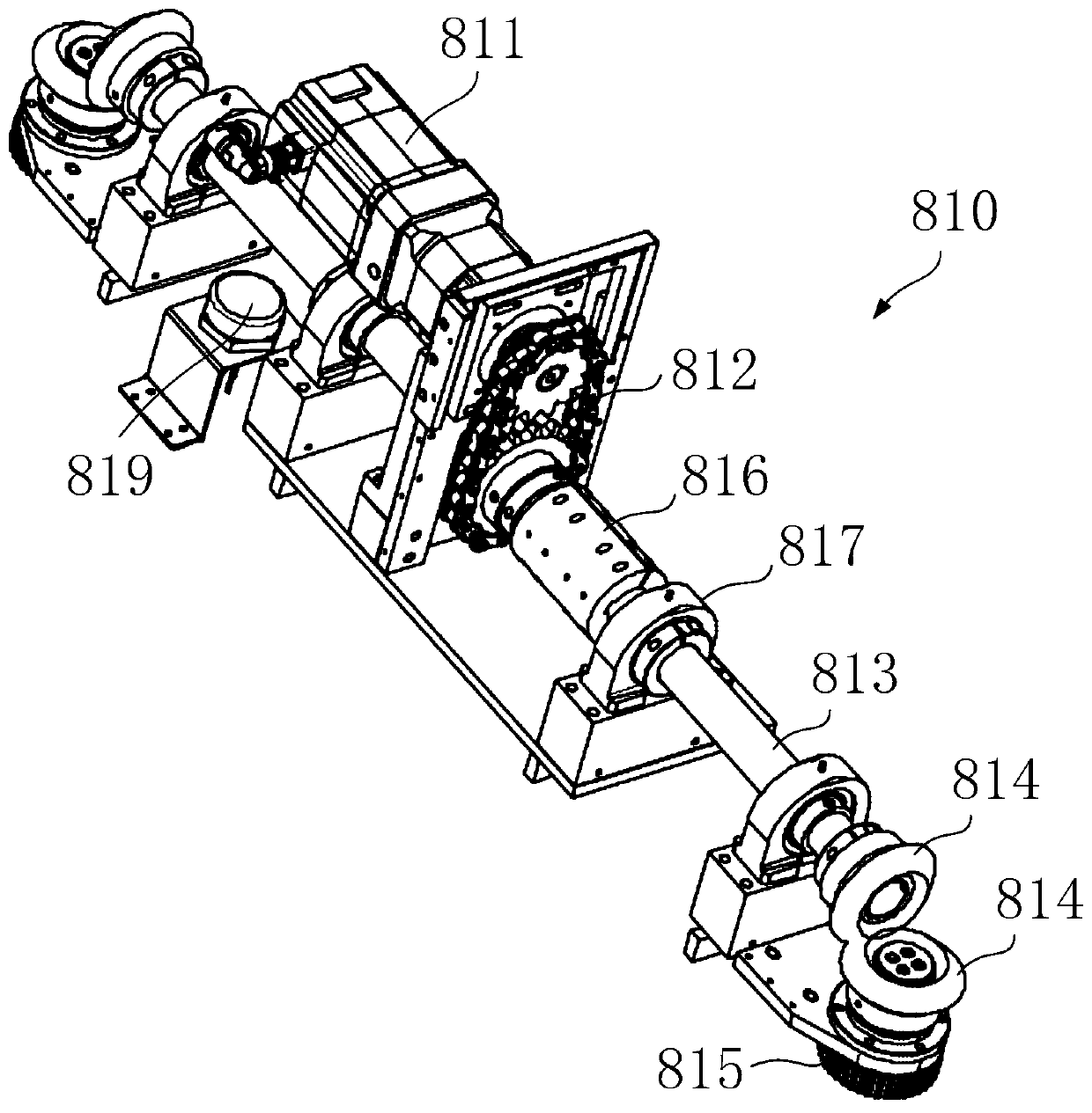
[0056] Embodiment 1. Laterally transfer the main body 810:

[0057] like figure 2 , image 3 As shown, the lateral transfer body 810 includes a lateral driving member 811, a transmission shaft 813, a reversing structure 814, and a driving gear 815; wherein,

[0058] The horizontal driving member 811 drives the transmission shaft 813 to rotate; the transmission shaft 813 is installed perpendicular to the direction of the track 8103; the end of the transmission shaft 813 is connected to the reversing structure 814; The gear 815 rotates, and the driving gear 815 rotating shaft is vertical to the motion direction of the lifting platform body 840; the driving gear 815 is in motion with the rack 818 provided on the direction of the moving track of the drive transfer assembly 800; driven by the transverse driving member 811, so that The driving gear 815 drives the lifting platform body 840 to reciprocate relative to the rack 818 along the track 8103 . In this embodiment, the late...

Embodiment 2

[0066] Embodiment 2, lifting platform body 840:

[0067] like Figure 4-Figure 9 As shown, the lifting platform body 840 includes a first placement plate 841, a second placement plate 842, a lifting drive member, a lifting guide assembly, and a base frame; wherein,

[0068] The first placement plate 841 and the second placement plate 842 are used to limit and carry the battery assembly; in this embodiment, the first placement plate 841 is used to limit the end and side of the battery assembly, and the second placement plate 842 is used to To limit the side of the battery assembly; the first placement plate 841 and the second placement plate 842 are equipped with a "U"-shaped positioning and limiting structure to form the positioning and lifting of the battery assembly.

[0069] The fixed portion of the lifting drive and the lifting guide assembly is fixed on the base frame; the lifting guide assembly is connected to the first placement plate 841 and the second placement plate...

Embodiment 3

[0074] Embodiment 3, floating column body 650 and clamping mechanism body 660:

[0075] like Figure 10-18 As shown, the floating column body 650 connects the fixed substrate and the floating substrate; the clamping mechanism body 660 is installed between the fixed substrate and the floating substrate; wherein;

[0076] The floating column body 650 is used to floatingly support the floating substrate, so that the floating substrate can float up and down and horizontally relative to the fixed substrate;

[0077] The clamping mechanism body 660 is used to fix the floating substrate, so as to counteract the lateral force brought by the floating column body 650 during the power exchange process.

[0078] In this embodiment, combining 10, Figure 11 As shown, the floating substrate is the first placement plate 841 , and the fixed substrate is the first fixed plate 847 . In one embodiment, combined with Figure 10-Figure 14 As shown, the floating substrate includes a first float...


PUM


Abstract

The invention provides a battery-replacement moving and carrying device capable of achieving floating without lateral force. The battery-replacement moving and carrying device comprises a transverse moving and carrying body, a lifting table body, a fixed base plate, a floating base plate, floating column bodies and clamping mechanism bodies. The transverse moving and carrying body is used for providing driving force for transverse conveying of a battery assembly. The lifting table body is used for elevating the battery assembly on the floating base plate. The floating column bodies are used for floating and supporting the floating base plate so that the floating base plate can float vertically and horizontally relative to the fixed base plate. The clamping mechanism bodies are used for fixing the floating base plate so that the lateral force brought by the floating column bodies in the battery replacement process can be offset. The battery-replacement moving and carrying device is ingenious in structure and reasonable in design, the vertical-direction size of the moving and carrying device is reduced, stable rising and falling are achieved in the battery replacement process, and meanwhile the battery assembly is allowed to float in all directions; and the requirement for positioning of the device is lowered, the lateral force generated in the floating process is eliminated, unnecessary collisions of the battery assembly are avoided, the requirement of new energy vehicles for rapid battery replacement is met, and application and popularization are convenient.

Description

technical field [0001] The invention belongs to the field of quick replacement batteries, and in particular relates to a battery replacement and transfer device with floating without lateral force. Background technique [0002] With the increasing use of various types of new energy vehicles such as electric vehicles and hybrid vehicles, technologies related to quick battery replacement have become more and more people's attention and research topics. How to timely and effectively provide power supply for electric vehicles with insufficient power has become a matter of great concern to both manufacturers and car owners. By establishing a battery exchange system to exchange electricity for electric vehicles, that is, directly replacing the exhausted power battery with a fully charged power battery, the power supply can be completed within minutes, so the battery exchange method is a kind of A very efficient way of supplementing electrical energy. [0003] Although a variety ...

Claims


Application Information

Patent Timeline
Patent Type & Authority Applications(China)
IPC IPC(8): B60S5/06B60L53/80
CPCB60L53/80B60S5/06Y02T10/70Y02T10/7072
Inventor 肖申牟东戴有发叶庆丰吴小平孙庆
Owner BOZHON PRECISION IND TECH CO LTD
Why Eureka
Try Eureka