Tempered curved glass and equipment with stress pattern weakening effect

A glass tempering and stress spot technology, applied in the direction of glass tempering, glass manufacturing equipment, glass production, etc., can solve the problems affecting the appearance and use effect of glass, and achieve the effect of improving appearance and quality and reducing fluid resistance.

Pending Publication Date: 2019-10-25
LUOYANG LANDGLASS TECH CO LTD
View PDF1 Cites 1 Cited by
  • Summary
  • Abstract
  • Description
  • Claims
  • Application Information

AI Technical Summary

Problems solved by technology

like figure 1 As shown, the main reason for the occurrence of stress spots is: the use of wind box air grid technology will leave obvious

Method used


Image

  • Tempered curved glass and equipment with stress pattern weakening effect
  • Tempered curved glass and equipment with stress pattern weakening effect
  • Tempered curved glass and equipment with stress pattern weakening effect

Examples


Embodiment 1

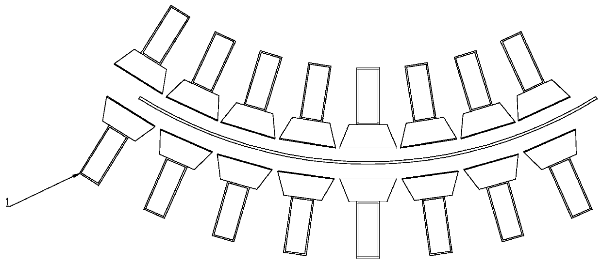
[0063] When processing toughened glass, the main air supply duct 1 and the flexible air grid unit 2 Figure 5 Arranged in the center, at both ends of the main air supply duct, there is a variable arc mechanism (for the variable arc mechanism, please refer to the glass bending and forming mechanism in CN201220306623.8). When the arc changing mechanism bends, the flexible air grid unit 2 will also change the arc accordingly.

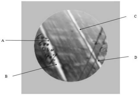
[0064] This embodiment provides a curved glass tempering device with a stress spot weakening effect, refer to image 3 , used for flexible shaft bending glass tempering, the equipment includes a flexible air grid, the flexible air grid is composed of one or more flexible air grid units 2, the flexible air grid unit 2 is a bendable flexible tubular structure penetrating inside, the flexible air grid The grid unit 2 is provided with a plurality of air outlets 22 and air inlets 21 communicating with its internal space, the air outlets 22 facing the glass to ...

Embodiment 2

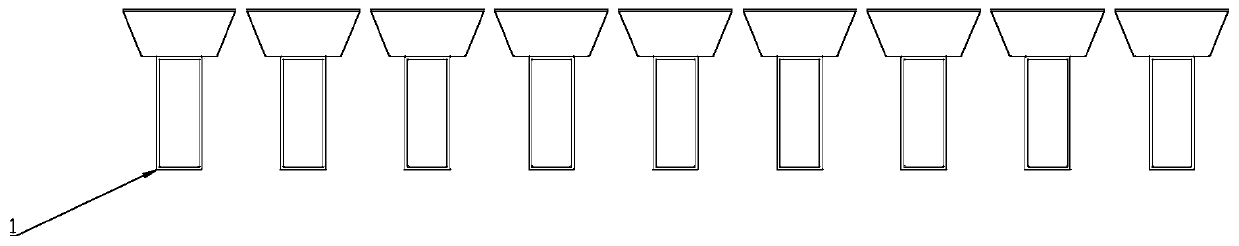
[0072] This embodiment is further defined on the basis of Embodiment 1. A plurality of flexible air grid units 2 are arranged in parallel between the gaps between the flexible shaft roller tables, and the main air supply duct 1 is located on the side of the flexible air grid units 2 away from the glass to be processed. , the parallel main air supply duct 1 and the multiple parallel flexible air grid units 2 are projected in the vertical direction to intersect with each other to form a network, and the main air supply duct 1 and the flexible air grid unit 2 are projected from the intersection point of the projection to the air inlet 21 connected, refer to Figure 5 ; The arc-changing mechanism located at both ends of the main air supply duct 1 arranged in parallel drives the flexible air grid unit 2 to bend with the arc-changing mechanism when the glass to be processed is bent and formed. The axial ends of the flexible air grille unit 2 are closed structures to ensure that the ...

Embodiment 3

[0076] On the basis of Embodiment 1, this embodiment provides a curved glass tempering device with an air outlet mechanism, which also includes an air outlet mechanism. The air outlet mechanism is arranged on the flexible air grille unit 2, including The fluid smooth structure and / or the outlet airflow directional stabilization structure arranged on the outer wall of the flexible air grille unit 2; the fluid smooth structure is used to reduce the resistance of the air flow in the flexible air grille, and the outlet airflow directional stability structure is used to control the jet Constrains the direction of the airflow while making the velocity and flow of the airflow more uniform.

[0077] The smooth fluid structure and the directional stability structure of the outlet airflow can be arranged alternatively or cooperatively.


PUM


Abstract

The invention relates to the technical field of glass tempering, in particular to a method for weakening a stress pattern of tempered curved glass and tempered curved glass equipment of the method. Anoriginal split type air box is replaced by a penetrating continuous reversible deformed cavity as a wind grid; a fluid smoothing structure is arranged in the cavity to reduce fluid resistance; a windair flow orienteering stabilizing structure is arranged outside the cavity for constraining the direction of the jet air flow, the flow velocity and the flow rate; and a docking device which can be changed according to the change of curvature of the curved surface of the cavity is arranged between the cavity and an air supply source. The wind grid composed of each of the independent wind boxes inthe wind grid is replaced by a flexible wind grid which mutually penetrates to form the continuous wind grid perpendicular to the moving direction of the glass, the wind grid blows the tempered glassin the glass movement, the strip-shaped stress pattern left in the wind grid cooling process of the prior art can be eliminated, and the appearance and quality of the tempered glass is greatly improved.

Description

technical field [0001] The invention relates to the technical field of flexible shaft bending glass tempering, in particular to a curved glass tempering device with a stress spot weakening effect. Background technique [0002] In the production process of tempered glass, the glass enters the tempering section after being heated in a roller-type heating furnace. However, during the tempering process, stress spots (commonly known as wind spots) are often left on the glass due to uneven blowing. Tempered glass wind As an indicator of appearance quality, wind spot has attracted more and more attention. In order to reduce wind spot as much as possible, technicians in this industry have adopted various methods, such as accelerating the speed of glass out of the furnace, optimizing the layout of air holes, and laterally swinging the air grille, etc. . However, the formation of wind spots is complicated. In addition to the need to consider the formation of uniform cooling in the wi...

Claims


Application Information

Patent Timeline
IPC IPC(8): C03B27/044
CPCC03B27/044C03B27/0404C03B27/0447C03B27/0413C03B27/0442
Inventor 赵雁张克治张喜宾
Owner LUOYANG LANDGLASS TECH CO LTD
Why Eureka
Try Eureka