Mounting structure for decorative cover of range hood

A technology for a range hood and an installation structure, applied in the field of range hoods, can solve problems such as the falling off of the decorative cover, the inability to install the decorative cover, and the damage to the appearance of the decorative cover, so as to reduce the installation accuracy, realize the seamless connection, and avoid the left and right deviation. the effect of disengagement

Active Publication Date: 2019-10-25
NINGBO FOTILE KITCHEN WARE CO LTD
View PDF4 Cites 16 Cited by
  • Summary
  • Abstract
  • Description
  • Claims
  • Application Information

AI Technical Summary

Problems solved by technology

The following problems exist in the installation of the existing drawable decorative cover: 1. The gap between the decorative cover and the ceiling is too large, which affects the appearance; 2. Before installing the decorative cover, the range hood shell needs to be removed first, which is inconvenient to install; 3. Connect the decorative cover to the hook or the wall from the outer surface of the decorative cover by screwing, which destroys the appearance of the decorative cover
The installation structure has the following problems in actual use: ①. The installation accuracy of the hook is relatively high
In the vertical direction, the distance between the hook and the ceiling needs to be measured by the installer and fixed according to the design requirements. If the hook is installed too high, the decorative cover cannot be installed; if it is too low, there will be a gap between the decorative cover and the suspended ceiling, which will affect the appearance
②, easy to fall off
In addition, the motor of the range hood has self-excited vibration during high-speed operation, and the impeller of the range hood is affected by the manufacturing process and the user's working conditions, and there is a certain dynamic balance deviation. There is a small vibration
Long-term vibration accumulation makes the lock tongue and hook shift to the left or right or forward until the two are disengaged, causing the decorative cover to fall off
③, fatigue fracture
The limit piece (also called connecting shaft) between the bracket and the lock tongue in the lock, usually adopts high-efficiency and low-cost pressure riveting process to quickly connect the two in mass production. The limit piece can resist high shear force However, it is not resistant to pull-out force. In this structure, the limiter is subject to pull-out force for a long time and the above-mentioned long-term low-frequency vibration, which makes the limiter fatigue loose and fall off, and finally causes the decorative cover to fall.

Method used


Image

  • Mounting structure for decorative cover of range hood
  • Mounting structure for decorative cover of range hood
  • Mounting structure for decorative cover of range hood

Examples


Embodiment 1

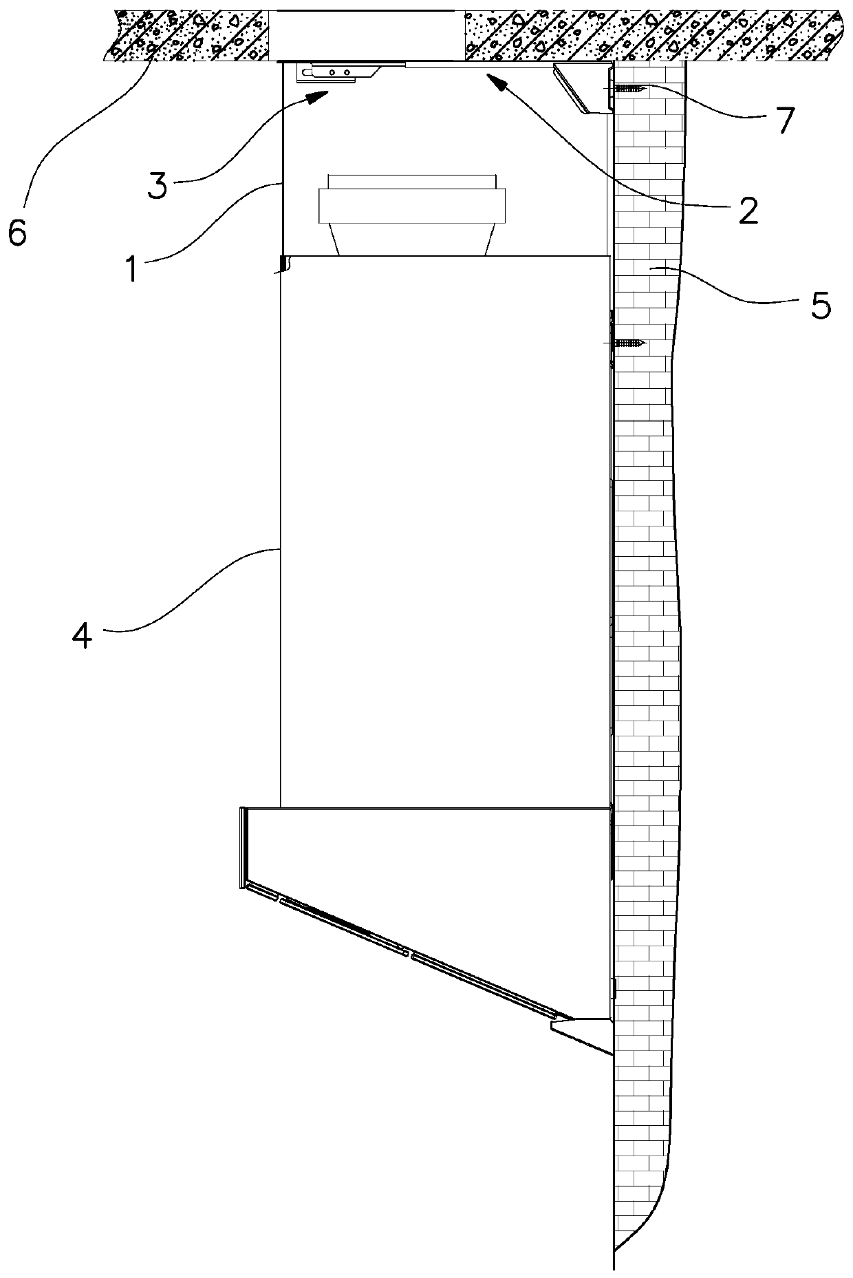
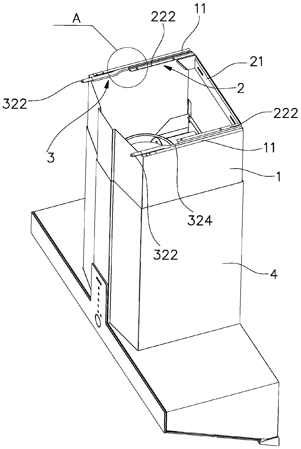
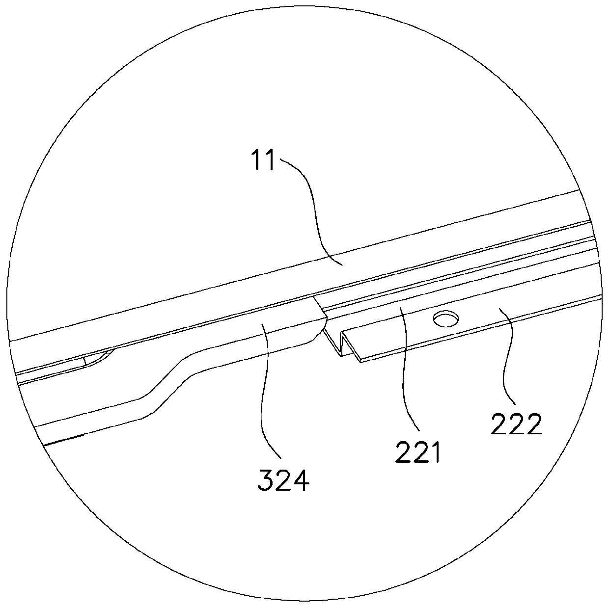
[0038] like Figures 1 to 14 As shown, the decorative cover installation structure of the range hood in this embodiment includes a decorative cover 1 , a hook 2 and a lock 3 . The decorative cover 1 is arranged on the top of the range hood casing 4 and can be pulled up and down. The lock 3 includes a lock bracket 31 and a lock tongue 32. The lock bracket 31 is fixed on the decoration cover 1, and the lock tongue 32 is movable forward and backward. On the lock bracket 31 and cooperate with the hook 2 . The hook 2 includes a hanging frame 21 and a hanging plate 22 arranged at the left and right ends of the hanging frame and extending forward. Hanger 21 is fixed on the body of wall 5 by screw 7, and hanging board 22 has the lower U-shaped groove 221 of opening upwards, and the inner upper edge of lower U-shaped groove 221 bends inwardly to form inner flanging 222, and inner flanging 222 and The kitchen ceiling is fitted and fixed in 6 phases. The left and right side upper edge...

Embodiment 2

[0044] like Figures 15 to 19 As shown, the operating piece 322 and the locking piece 324 of the lock tongue 32 in this embodiment are respectively located on the left and right sides of the top of the mounting piece 323, the operating piece 322 protrudes laterally outside the decorative cover 1, and the locking piece 324 is always in line with the upper The bent pieces 11 are separated from each other. The rest of the structure of this embodiment is the same as that of Embodiment 1, and will not be further described here.


PUM


Abstract

The invention discloses a mounting structure for a decorative cover of a range hood. The structure comprises the decorative cover, a hook and lock catches, wherein hanging plates at the left end and the right end of the hook are provided with lower U-shaped grooves with upward openings, the upper edges of the inner sides of the lower U-shaped grooves are bent inwards to form inner flanges attachedand fixed to a ceiling of a kitchen, the two lock catches are arranged on the left side and the right side of the interior of the decorative cover, and a bolt is provided with upper U-shaped grooveswith downward openings and is reversely bucked and limited on the lower U-shaped grooves. The structure has the advantages that according to the mounting structure for the decorative cover of the range hood, the hanging plates and the bolt are reversely buckled and limited through the U-shaped grooves, so that the left and right movement of the bolt is limited by the hanging plates, and the left and right offset separation of the decorative cover is avoided; and the inner flanges of the lower U-shaped grooves of the hanging plates are attached and fixed to the ceiling of the kitchen, in the vertical direction, the distance between the hook and the ceiling does not need to be measured by mounting personnel and is fixed according to design requirements so that the mounting precision of the hook can be increased, and the decorative cover can be ensured to be smoothly arranged.

Description

technical field [0001] The invention relates to a range hood, in particular to a decorative cover installation structure of the range hood. Background technique [0002] The decorative cover of the range hood is used to cover the air outlet cover and air duct on the top of the range hood, which plays a role of beauty and decoration. The decorative cover can usually be pulled out from the top of the range hood, and can be adjusted according to the height of the user's house. height adjustment. The following problems exist in the installation of the existing drawable decorative cover: 1. The gap between the decorative cover and the ceiling is too large, which affects the appearance; 2. Before installing the decorative cover, the range hood shell needs to be removed first, which is inconvenient to install; 3. The decorative cover is connected to the hook or the wall from the outer surface of the decorative cover by screwing, which destroys the appearance of the decorative cove...

Claims


Application Information

Patent Timeline
Patent Type & Authority Applications(China)
IPC IPC(8): F24C15/20
CPCF24C15/20
Inventor 袁柯铭
Owner NINGBO FOTILE KITCHEN WARE CO LTD
Why Eureka
Try Eureka