
Distributed acoustic sensing

A technology of optical sensing and sensing area, which is applied in the field of optical sensors and can solve problems such as signal fading

Active Publication Date: 2019-10-25
FOCUS SENSORS LTD
View PDF9 Cites 3 Cited by
  • Summary
  • Abstract
  • Description
  • Claims
  • Application Information

AI Technical Summary

Problems solved by technology

Since the scatterer positions are random, this addition can be destructive and result in no return signal
Furthermore, the scatterer position can change over time, which leads to a change in the summation and thus signal fading over time

Method used


Image

  • Distributed acoustic sensing
  • Distributed acoustic sensing
  • Distributed acoustic sensing

Examples


Embodiment Construction

[0077] Further details, aspects and embodiments of the invention will now be described, by way of example only, with reference to the accompanying drawings. Elements in the figures are illustrated for simplicity and clarity only and have not necessarily been drawn to scale. The same reference numerals have been included in the corresponding figures for easy understanding.

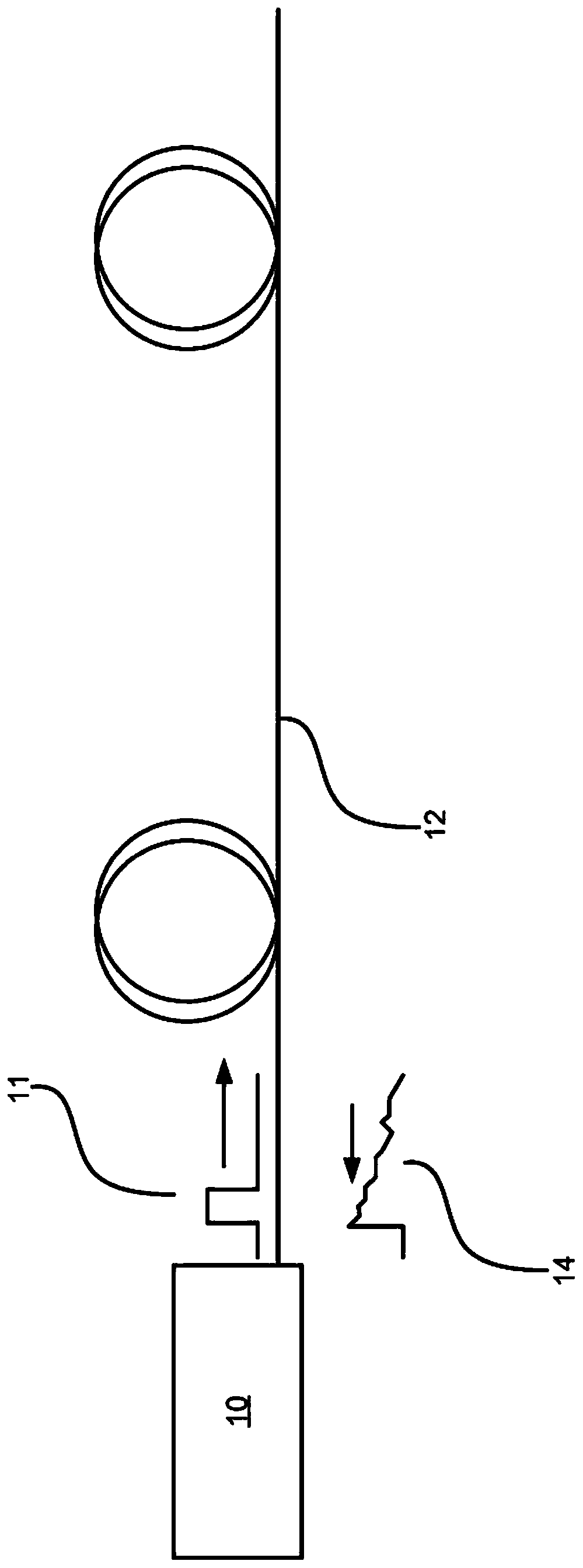
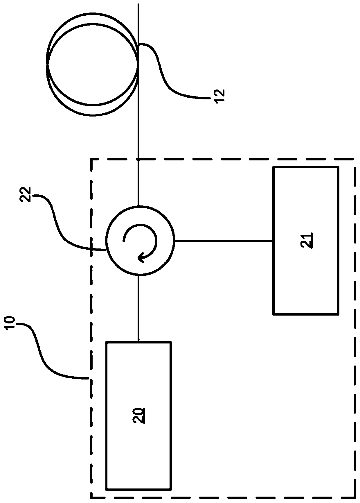
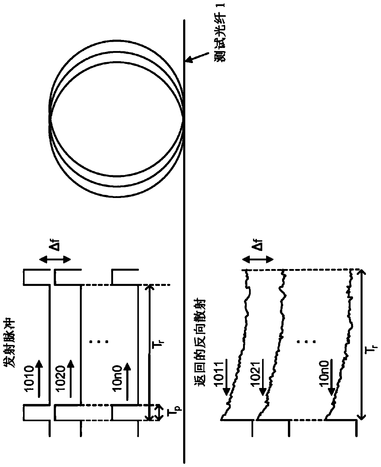
[0078] image 3 Schematic showing detection and backscatter pulses transmitted by and returned to interrogator 10 in a system with figure 1 and figure 2 is similar but configured to send a probe pulse as described below.

[0079]The transmitter sends a set of probe pulses 1010, 1020, 10n0 at different optical frequencies, each frequency being separated by Δf from its neighbors. The pulse width is shown as T p and the repetition rate is shown as T r . A series of backscattered pulses 1011, 1021, 10n0 also spaced apart by Δf are received at the receiver. Several hundred frequencies are available in a...


PUM


Abstract

Systems and methods for sensing changes in an optical sensing fibre, principally for detecting changes in strain. A plurality of optical probe pulses at different optical frequencies (f1, f2,... fn) spaced by deltaf are transmitted into the sensing fibre. Light backscattered from the optical sensing fibre may be mixed with delayed backscatter frequency shifted by deltaf+fm where fm is a heterodynefrequency. The backscattered or mixed light may be detected to determine changes in the sensing fibre. Deltaf may be chosen to optimise performance.

Description

technical field [0001] The present disclosure relates to optical sensors, and in particular, to distributed acoustic sensing utilizing fiber optic based sensors. Background technique [0002] Optical fiber based sensors are known for detecting various parameters, including acoustic signals, through stress changes in the optical fiber. Systems can be broadly characterized as utilizing discrete or distributed sensors. Discrete sensors typically position an optical cavity within the fiber at the desired sensor location. Variations in fiber stress lead to variations in the physical length of the optical resonant cavity, and thus, variations in the optical phase length of the cavity for optical signals propagating in the cavity. Detection of the output signal from the optical resonant cavity allows the phase length variation to be deduced and, thus, the parameter of interest to be detected. Each fiber can provide several sensing locations to allow simultaneous measurement of m...

Claims


Application Information

Patent Timeline
Patent Type & Authority Applications(China)
IPC IPC(8): G01D5/353G01H9/00
CPCG01D5/35303G01D5/35335G01D5/35364G01H9/004H04B10/25
Inventor 爱德华·阿尔弗雷德·登齐尔·奥斯汀赵渭忠
Owner FOCUS SENSORS LTD
Learn More