Submersible Pump Monitoring

a submersible pump and monitoring technology, applied in the direction of liquid/fluent solid measurement, survey, fluid removal, etc., can solve the problems of high pump damage, high maintenance cost, time-consuming and disruptive to the operation,

Active Publication Date: 2017-01-19
SILIXA
View PDF6 Cites 21 Cited by
  • Summary
  • Abstract
  • Description
  • Claims
  • Application Information

AI Technical Summary

Benefits of technology

[0010]In order to address the above noted problems, embodiments of the present invention use distributed acoustic sensing to monitor the fluid level in an ESP activated well so as to monitor the condition and performance of the ESP. Embodiments of the invention use the ESP as an acoustic source in order to monitor the annulus fluid level within the well, and also to monitor the frequency of the ESP. Additionally, embodiments of the present invention may use distributed acoustic sensing to monitor the flow rates of the production fluid above and below the ESP to determine the pump's efficiency. In particular, some embodiments utilise one or more optical fibers to measure the acoustic waves generated by the ESP, wherein the fiber cabling has already been deployed along the length of the well. As such, the present invention is a non-invasive, in-situ method for monitoring the condition and performance of an ESP.

Problems solved by technology

In the case of an ESP, it is important to monitor the fluid level in the well to ensure that the ESP is surrounded by liquid to prevent it from overheating or running dry, which can lead to extensive pump damage and considerable repair costs for the pump operators.
This can be costly, time intensive and disruptive to the operation of the oil well.
In addition, such techniques only provide measurements at discrete points in time, and are not conducive to continuous or almost-continuous monitoring.

Method used


Image

  • Submersible Pump Monitoring
  • Submersible Pump Monitoring
  • Submersible Pump Monitoring

Examples


Embodiment Construction

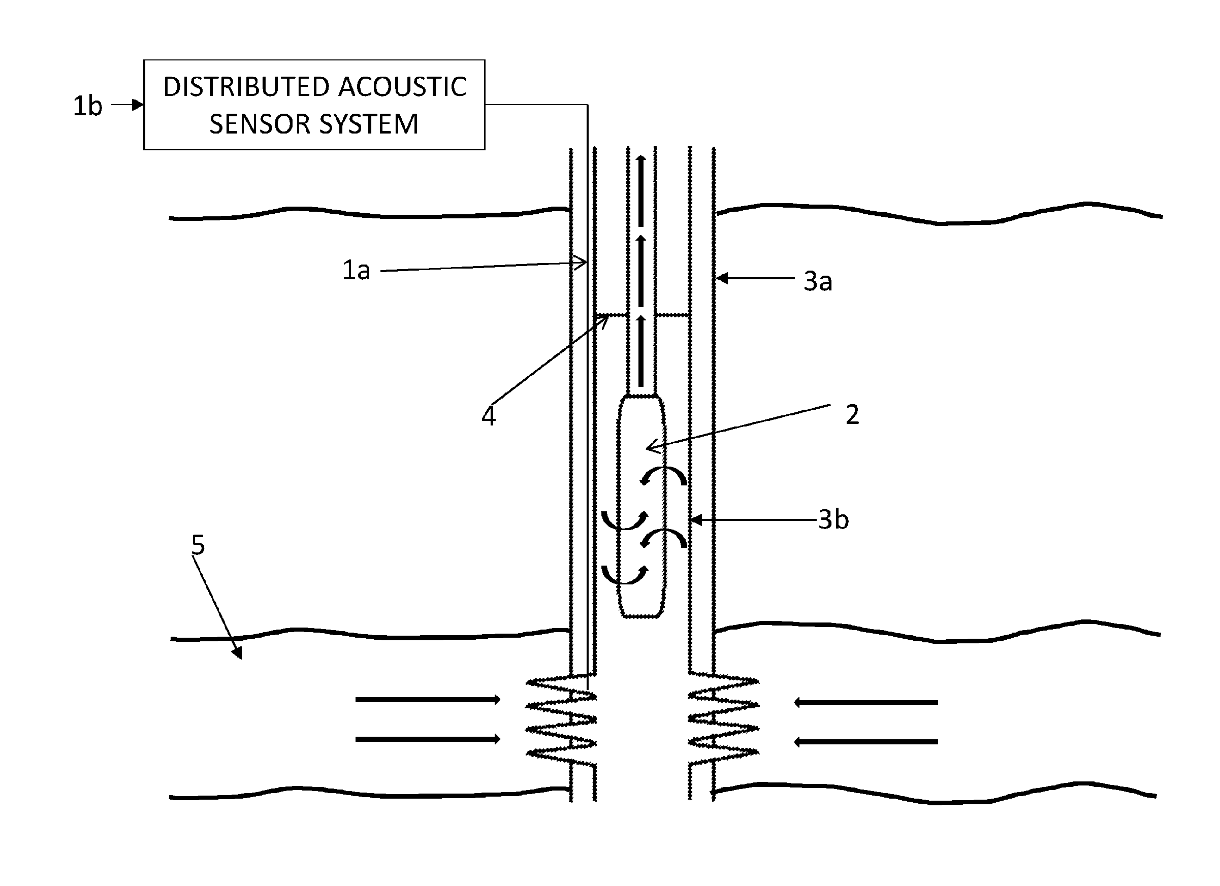
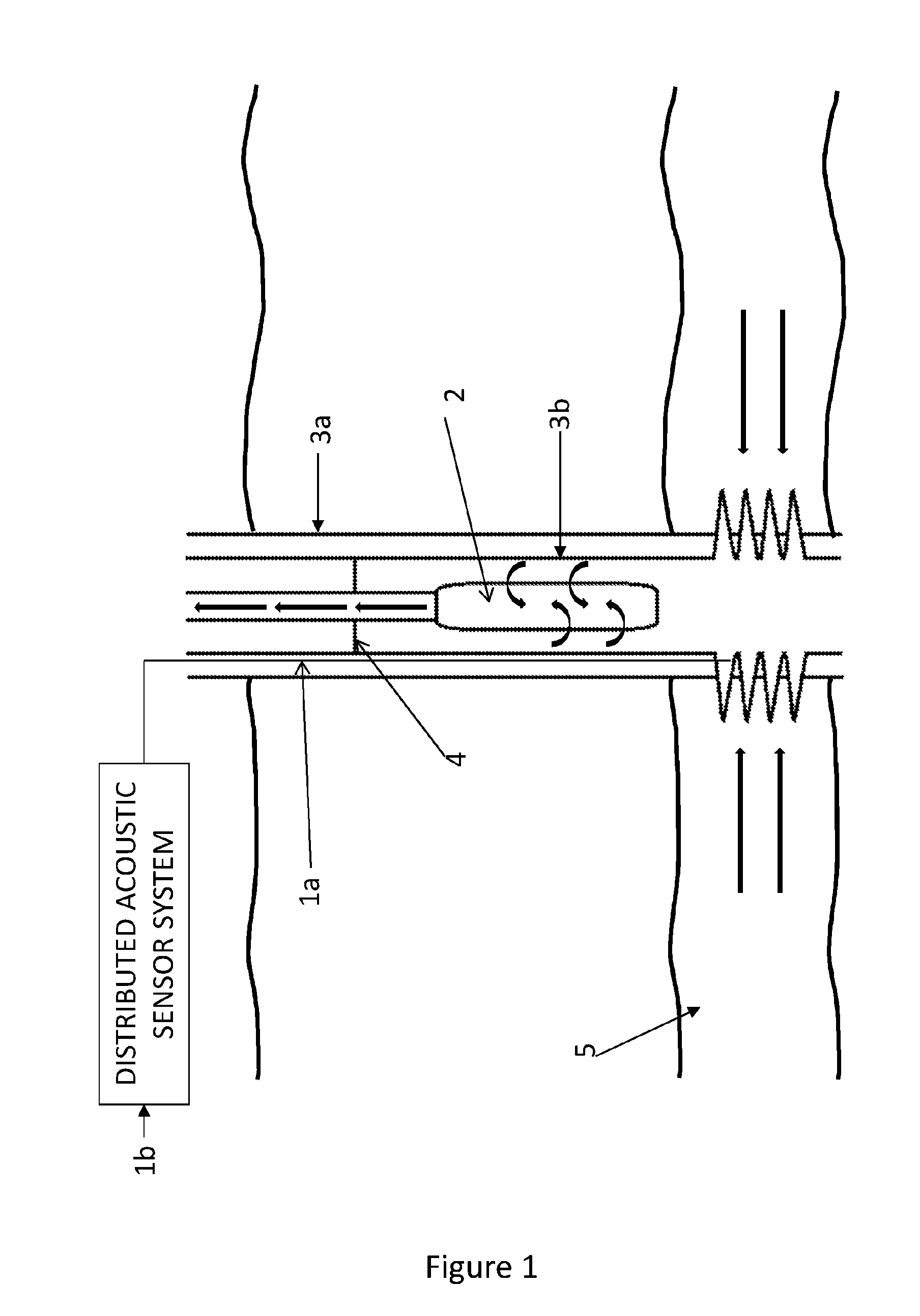
[0036]In a particular embodiment of the invention, described here in order to provide an example of a preferred implementation of the present invention, an optical fibre distributed acoustic sensor is provided along an ESP activated well in order to detect the propagation of acoustic waves generated by the ESP, and thus monitor the annulus fluid level of the well, as will be described. In use, as known in the art, an ESP is submerged into the production fluid and used to increase the flow rate of production fluids. The ESP decreases the pressure at the bottom of the well by increasing the drawdown in order to artificially ‘lift’ the production fluid from its reservoir to the surface.

[0037]FIG. 1 illustrates a typical deployment scenario for embodiments of the present invention. Here, a wellbore 3a has been drilled down into gasoline producing rock 5, and a casing 3b installed therein. During completion of the wellbore 3a, a submersible pump, such as an electrical submersible pump (E...


PUM


Abstract

In order to address the above noted problems, embodiments of the present invention use distributed acoustic sensing to monitor the fluid level in an ESP activated well so as to monitor the condition and performance of the ESP. Embodiments of the invention use the ESP as an acoustic source in order to monitor the annulus fluid level within the well and to monitor the frequency of the ESP. Additionally, embodiments of the present invention may use distributed acoustic sensing to monitor the flow rates of the production fluid above and below the ESP to determine the pump's efficiency. In particular, some embodiments utilise one or more optical fibers to measure the acoustic waves generated by the ESP, wherein the fiber cabling has already been deployed along the length of the well. As such, the present invention is a non-invasive, in-situ method for monitoring the condition and performance of an ESP.

Description

TECHNICAL FIELD[0001]Some embodiments of the invention relate to the monitoring of submersible pumps, such as Electrical Submersible Pumps (ESPs), deployed in-well. In addition, some embodiments of the present invention relate to fluid level detection in oil wells using an optical fibre based distributed acoustic sensor.BACKGROUND TO THE INVENTION AND PRIOR ART[0002]Artificial lift methods are commonly used to increase the flow rates of liquids in production wells that have insufficient pressure to bring the production fluids to the surface. This is often the case, for example, for crude oil or a mature well wherein the well pressure has decreased. The artificial lift methods used include injecting gas or water further down the well, or introducing a mechanical device inside the well to artificially increase the well pressure, for example, an Electrical Submersible Pump (ESP).[0003]Where a mechanical device such as an ESP is deployed inside a well, it is necessary to monitor the con...

Claims


Application Information

Patent Timeline
Patent Type & Authority Applications(United States)
IPC IPC(8): E21B47/00G01F23/296E21B43/12E21B47/04E21B47/10
CPCE21B47/0007E21B47/042G01F23/2968E21B43/128E21B47/101E21B47/008E21B47/047E21B47/107E21B47/135G01H9/004E21B43/12
Inventor CLARKE, ANDREWFINFER, DANIELMAHUE, VERONIQUEPARKER, TOMFARHADIROUSHAN, MAHMOUD
Owner SILIXA
Why Eureka
Try Eureka