Eureka AIR delivers breakthrough ideas for toughest innovation challenges, trusted by R&D personnel around the world.

Method of measuring acoustic distribution and distributed acoustic sensor

a technology of acoustic distribution and acoustic sensor, which is applied in the direction of vibration measurement in solids, instruments, specific gravity measurement, etc., can solve the problems of complex structure of cotdr and high cost of optical components

Active Publication Date: 2013-12-19
THE FUJIKURA CABLE WORKS LTD
View PDF11 Cites 20 Cited by
  • Summary
  • Abstract
  • Description
  • Claims
  • Application Information

AI Technical Summary

Benefits of technology

The patent text describes a method and device for measuring sound distribution without using a specific detection method. This makes it easier to measure the acoustics of a space without needing special equipment.

Problems solved by technology

However, a COTDR has a complex structure and requires a lot of expensive optical components.

Method used


Image

  • Method of measuring acoustic distribution and distributed acoustic sensor
  • Method of measuring acoustic distribution and distributed acoustic sensor
  • Method of measuring acoustic distribution and distributed acoustic sensor

Examples


examples

[0111]Hereinbelow, an Example of the present invention is described.

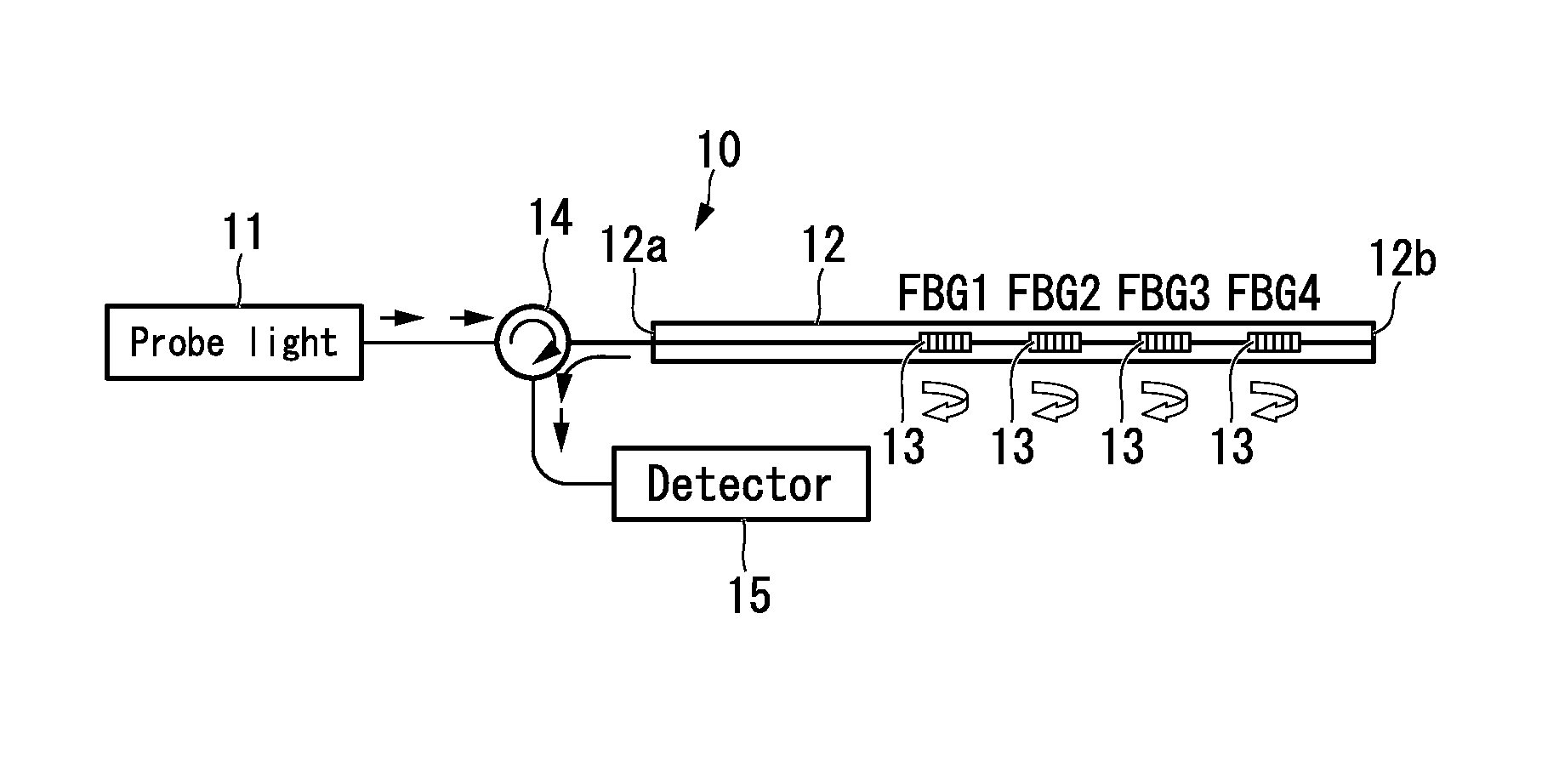
[0112]In FIG. 15, experimental equipment used in the present example is shown. In this experimental equipment, in addition to the distributed acoustic sensor similar to shown in FIG. 13, piezo stages 21, 22 which artificially inducing vibration near the FBGs are provided. In addition, in order to control respective piezo stages 21, 22, a piezo controller 20 including a function generator 20a is connected. At each of the two FBGs, one piezo stage is provided. As a consequence, in the present experimental equipment, the FBG1 and the FGB2 can be vibrated independently. Note that as the optical fiber 12, an optical fiber is used that has a cladding of made pure silica glass, a core made of germanium-doped silica glass, relative refractive index difference (Δ) between the core and the cladding of approximately 0.3%, a cladding diameter of 125 μm, and a diameter of 155 μm with polyimide-coated. Moreover, the temperature d...


PUM


Abstract

Optical pulses are output from a light source to an optical fiber at one selected emission wavelength, a reflection light reflected at a fiber Bragg grating at the optical fiber is received at an optical receiver and is converted to a reflection signal by an optical to electrical conversion, a fiber Bragg grating which reflects the reflection light is identified by the signal processing unit when an intensity of the reflection signal obtained by the optical receiver is over a predetermined threshold value, and a measurement step that calculates acoustic frequencies at the fiber Bragg grating based on a temporal change of the intensity of the reflection signal at the fiber Bragg grating is repeated more than two times while changing an emission wavelength of the light source. The acoustic frequency at each fiber Bragg grating is calculated to determine an acoustic distribution along a longitudinal direction of the fiber.

Description

[0001]This application is a non-provisional application claiming priority to and the benefit of U.S. provisional application No. 61 / 654,472, filed Jun. 1, 2012. The entire contents of which are incorporated herein by reference.BACKGROUND OF THE INVENTION[0002]1. Field of the Invention[0003]The present invention relates to a method of measuring an acoustic distribution and a distributed acoustic sensor.[0004]2. Description of Related Art[0005]In order to search and extract resources such as oil or gas (natural gas or shale gas), distributed measurement technologies using an optical fiber sensor are utilized. As an optical fiber sensor, there are Distributed Temperature Sensing (DTS), Distributed Strain Sensing (DSS), Distributed Acoustic Sensing (DAS), and so on.[0006]For example, in “First Downhole Application of Distributed Acoustic Sensing (DAS) for Hydraulic-Fracturing Monitoring and Diagnostics,” M. M. Molenaar et al., Society of Petroleum Engineers, SPE 140561, a distributed ac...

Claims


Application Information

Patent Timeline
Patent Type & Authority Applications(United States)
IPC IPC(8): G01H9/00
CPCG01H9/004G01H9/00
Inventor OMICHI, KOJITERADA, YOSHIHIROTANAKA, DAIICHIRO
Owner THE FUJIKURA CABLE WORKS LTD
Why Eureka
Eureka Blog
Learn More