Laying forming mold for resin-matrix composite battery case of new-energy automobile

A technology for new energy vehicles and composite materials, which is applied in the field of resin matrix composite material battery box placement molding molds for new energy vehicles, and composite material placement molding mold fields, which can solve the problem that dimensional accuracy and structural accuracy are difficult to guarantee, and there is a lack of mold design references. , the problem of demolding difficulty, etc., to achieve the effect of stable overall structure of the mold, not easy to deform the overall structure of the mold, and overcome the difficulty of demoulding

Active Publication Date: 2019-10-29
DALIAN UNIV OF TECH
View PDF11 Cites 1 Cited by
  • Summary
  • Abstract
  • Description
  • Claims
  • Application Information

AI Technical Summary

Problems solved by technology

[0009] The present invention is aimed at the design of the laying and molding mold for the resin-based composite material battery box, and aims at the lack of relevant mold design references, the difficulty of demolding after the resin-based composite material is cured and formed, the dimensional accuracy and structure of the composite material after laying and forming and curing and forming In order to solve the problems such as difficult to guarantee the accuracy, a battery box mold with simple structure, convenient demoulding, and the ability to guarantee the geometric accuracy and structural accuracy of the battery box was designed.

Method used


Image

  • Laying forming mold for resin-matrix composite battery case of new-energy automobile
  • Laying forming mold for resin-matrix composite battery case of new-energy automobile
  • Laying forming mold for resin-matrix composite battery case of new-energy automobile

Examples


Embodiment Construction

[0033] The specific implementation manners of the present invention will be further described below in conjunction with the technical solutions and accompanying drawings.

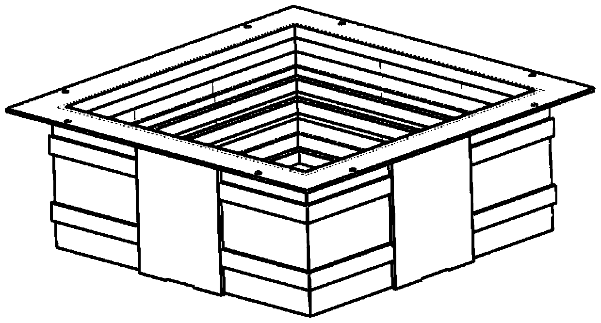
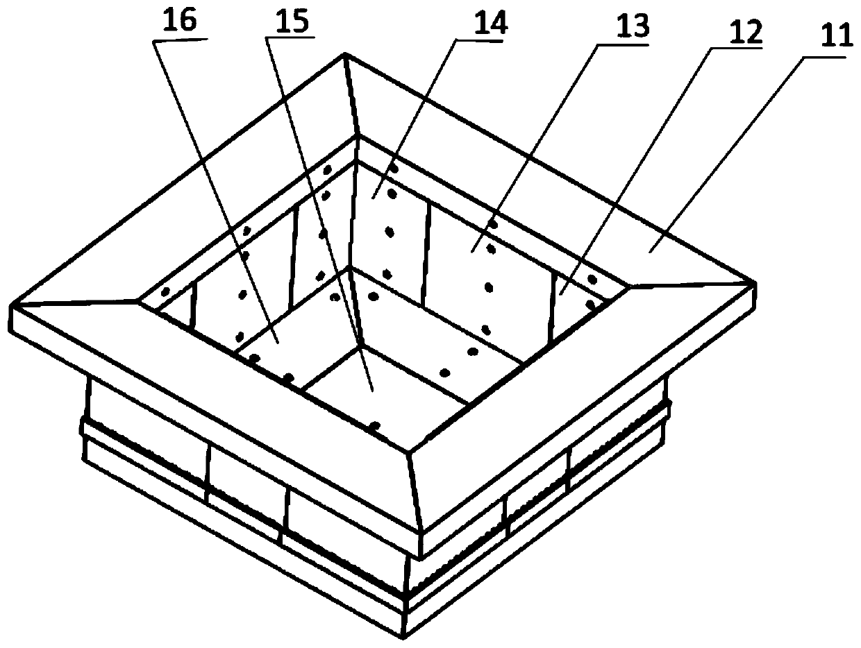
[0034] Such as image 3 , Figure 5 and Figure 6 As shown, a resin-based composite molding mold for new energy vehicles includes an inner mold, an outer mold and a fastening device;

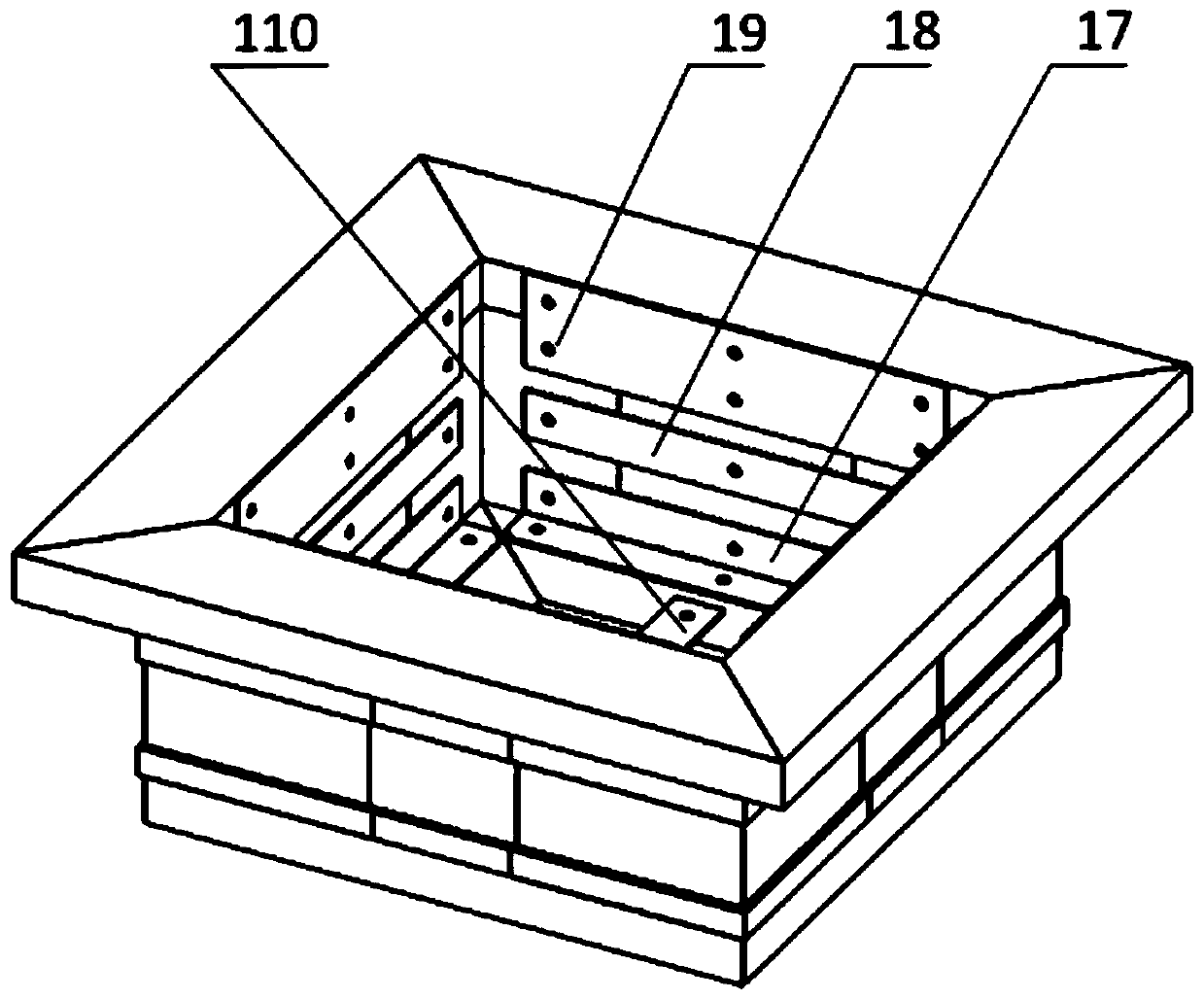
[0035] The inner mold includes inner flanging x 4, inner side panel-front x 4, inner side panel-middle x 4, inner side panel-back x 4, inner bottom four corners and inner bottom center x 1. Each part is provided with threaded holes so as to be connected as a whole through the cross-shaped connecting piece 110, the right-angled connecting piece 17, the inner plate connecting piece 18 and the inner plate-flange connecting piece 19;

[0036] When the inner mold is working, all parts of the inner mold should be combined into a whole. The combination sequence is as follows: 1. Connect the middle 15 of the inner bottom surface ...


PUM


Abstract

The invention discloses a laying forming mold for a resin-matrix composite battery case of a new-energy automobile. The laying forming mold for the resin-matrix composite battery case of the new-energy automobile comprises an inner mold body, an outer mold body and a fastening device. The inner mold body comprises an inner flange, a front inner side plate, a middle inner side plate, a rear inner side plate, an inner bottom central plate and four inner bottom corners. The outer mold body comprises a front outer side plate, a middle outer side plate, a middle outer side plate, a rear outer sideplate, and an outer bottom face. The mold comprising the inner mold body and the outer mold body can fully guarantee the geometric precision and structural precision; the detachable mold well overcomes the defect of complex and difficult demolding of resin-matrix composites; and the influence of concave and convex planes formed by a battery case reinforcing structure on the installation of the openable outer mold body is avoided.

Description

technical field [0001] The invention relates to a composite material laying molding die, which belongs to the technical field of composite material molding, and in particular to a resin-based composite material battery box laying molding die for new energy vehicles. Background technique [0002] In the field of new energy vehicles, resin-based composite materials are more and more widely used due to their small specific gravity, high specific strength, and fatigue resistance. Composite materials are highly designable and can be prepared into complex structures according to performance requirements Integral components enable the entire component to obtain better service performance. However, complex structural parts often bring great difficulties to the design of forming dies. Whether the die design is reasonable or not directly affects the forming quality and service performance of composite components. [0003] For the battery case of resin-based composite material used in...

Claims


Application Information

Patent Timeline
Patent Type & Authority Applications(China)
IPC IPC(8): B29C70/34B29C70/54B29C33/48B29C33/00B29C33/30
CPCB29C33/00B29C33/305B29C33/48B29C70/34B29C70/54
Inventor 王一奇靳晓博邵珠剑崔广朋于佳利张晓斌鲍永杰高航肖睿恒
Owner DALIAN UNIV OF TECH
Why Eureka
Try Eureka