
Installation method of energy-saving component

An installation method and component technology, applied in heating methods, space heating and ventilation details, household heating, etc., can solve the problems of decreased air volume, longer working hours of equipment, and increased energy consumption, so as to improve heat exchange efficiency , good energy-saving effect

Inactive Publication Date: 2019-10-29
豪宗(海口)新材料节能技术工程有限公司
View PDF4 Cites 0 Cited by
  • Summary
  • Abstract
  • Description
  • Claims
  • Application Information

AI Technical Summary

Problems solved by technology

However, although the existing installation methods can obviously have energy-saving effects in a short period of time, they will lead to increased energy consumption after long-term use. The reason is that although these energy-saving components have a large number of openings on the surface, they are simply covered. The installation will still hinder the suction of the heat exchange. When the air intake of the heat exchanger cannot meet its own power requirements for a long time, the air output will also decrease, which will eventually make the equipment work longer and cause heat exchange. The workload of the device will increase, but the energy consumption will become higher
However, although the existing installation method has obvious energy-saving effect in the early stage of heat exchanger operation, after a long period of operation, there is actually little difference in energy consumption compared with that without energy-saving components installed.

Method used


Image

  • Installation method of energy-saving component
  • Installation method of energy-saving component
  • Installation method of energy-saving component

Examples


Embodiment 1

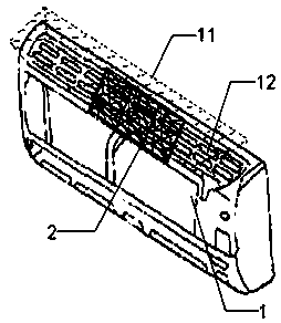
[0044] Such as Figure 1 to Figure 2 As shown, the energy-saving component 2 can be a sheet structure with a certain thickness, and the energy-saving component 2 has an effective use surface 21 , which needs to be arranged facing the heat exchange device when in use. exist image 3 shows the installation method of the energy-saving component 2 with openings on the wall-mounted air conditioner. During installation, it is necessary to check the area of ​​the effective airflow passage section 11 of the air inlet air path above the heat exchange equipment. If the area of ​​the energy-saving component is greater than / If the area of ​​the effective airflow passing section 11 of the air inlet airflow path of the heat exchange device is smaller than that, cutting / joining is required. The cut effective surface area of ​​the energy-saving component 2 should be at least not less than 30% of the effective airflow passage section 11 . The cut energy-saving component 2 is arranged in th...

Embodiment 2

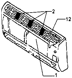
[0046] The same wall-mounted air conditioner, but if the energy-saving component 2 does not have openings, Figure 4 To show its installation method, it is also necessary to cut / assemble the energy-saving component 2 according to the same principle, so that the total effective use area of ​​the energy-saving component 2 meets the above requirements, but since the surface of the energy-saving component 2 does not have openings, the air volume passing through The energy-saving component 2 with openings on the surface, therefore, the energy-saving component 2 is divided into multiple pieces for installation, preferably according to Figure 4 The shown left, middle and right places are installed so that air turbulence can be formed between any two energy-saving components 2 . During installation, it is also necessary to ensure that there is a certain clearance from the air inlet 12. If the clearance requirement is not met, the energy-saving component 2 can still be bent to form an...

Embodiment 3

[0048] Figure 5 to Figure 6 The installation method of energy-saving components on the floor-standing air conditioner is shown. The air inlet device of the floor-mounted air conditioner heat exchange device 1 is also called a black hole fan. The front will inevitably cover a whole face shell to achieve the effect of protection and beauty. Therefore, the smoothness of the air intake directly in front of the black hole fan is completely hindered. Therefore, in order to ensure the air intake of the floor-standing air conditioner heat exchange device 1, the air conditioner manufacturer will open a plurality of vents on both sides and the bottom of the shell, such as the left air inlet 15, the lower air inlet 14, and the right air inlet 12. Because the air suction method of the floor-standing air conditioner is quite different from other air conditioners, it is necessary to calculate the effective air intake cross-sectional area of ​​the black hole fan before installation, and th...


PUM


Abstract

The invention discloses an installation method of an energy-saving component, and belongs to the field of energy conservation. The installation method of the energy-saving component comprises the following steps that the effective use area of the energy-saving component is cut and / or pieced together according to a certain ratio; and then the energy-saving component is arranged at an airflow routeon the periphery of a heat-exchanging device. The energy-saving component is made of a continuous far-infrared resonance material and is used for improving the heat exchange efficiency of the heat-exchanging device. According to the installation method of the energy-saving component, the energy-saving effect of the energy-saving component can be achieved truly, the heat-exchanging device cannot behindered and the burden is not formed due to the shape and the structure of the energy-saving component, the heat-exchanging device can run according to the power requirement of the heat-exchanging device all the time, and the energy-saving component has the characteristic of energy saving effect during either short time operation or long time operation.

Description

technical field [0001] The invention relates to an energy-saving method, in particular to an installation method of an energy-saving component. Background technique [0002] Refrigeration equipment plays an important role in modern life. As the trend of global warming becomes more and more significant, and the continuous high temperature weather continues to set new records, people's lives are increasingly separated from non-air-conditioning and refrigeration equipment. In addition, all large places have installed air-conditioning systems, and the proportion of electricity consumed by refrigeration equipment has been increasing. On the other hand, with the improvement of living standards, the proportion of refrigeration equipment such as refrigerated transport vehicles and refrigerators in daily life is also increasing. Although the prior art continuously researches and develops products for reducing energy consumption such as frequency conversion air conditioners and energ...

Claims


Application Information

Patent Timeline
Patent Type & Authority Applications(China)
IPC IPC(8): F24F13/30
CPCF24F13/30
Inventor 谭丁宁
Owner 豪宗(海口)新材料节能技术工程有限公司
Learn More