
Boosting lever and gear combination mechanism

A technology of gear combination and booster lever, applied in belt/chain/gear, mechanical equipment, transmission, etc., can solve the problems of not reducing energy consumption and high mechanical loss, and achieving reduced mechanical loss and high mechanical utilization rate , easy to use effect

Inactive Publication Date: 2012-07-25
陈周林
View PDF0 Cites 0 Cited by
  • Summary
  • Abstract
  • Description
  • Claims
  • Application Information

AI Technical Summary

Problems solved by technology

However, the above-mentioned gearboxes cannot achieve the purpose of reducing energy consumption due to the high mechanical loss caused by gear transmission.

Method used


Image

  • Boosting lever and gear combination mechanism
  • Boosting lever and gear combination mechanism
  • Boosting lever and gear combination mechanism

Examples


Embodiment Construction

[0025] The present invention will be further described below in conjunction with the accompanying drawings of the description.

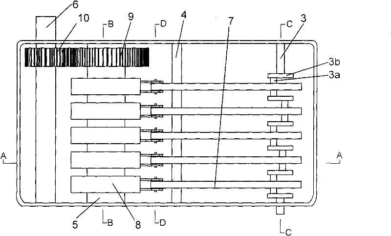
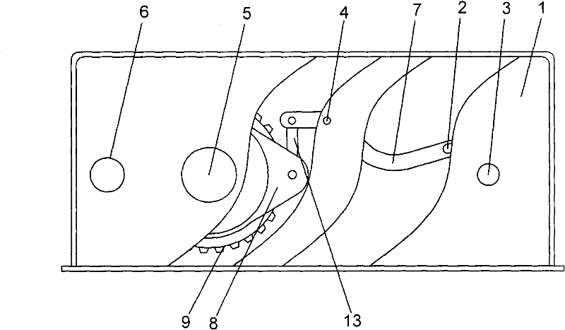
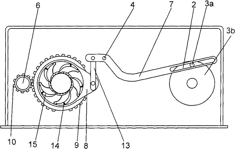
[0026] Such as figure 1 , figure 2 As shown, the booster lever gear combination structure includes an input shaft 3 and an output shaft 6 arranged on the gearbox housing 1, and the input shaft 3 passes through the booster lever 7, the stage tooth rotating shaft 5, and the speed regulation drive arranged in sequence. The wheel 9 and the speed-regulating driven wheel 10 are linked with the output shaft 6. The booster lever 7 is a duck-shaped lever, and the fulcrum shaft 4 on it is matched with the gear box shell 1, and one end of the long rod is connected through the sliding groove 2. To the input shaft 3, one end of the short rod is connected to the one-way movable tooth connecting arm wheel 8 co-located on the stage tooth rotating shaft 5 through the hinged connecting arm 13. Speed ​​driving wheel 9, speed regulating driven wheel 10, above-mention...


PUM


Abstract

The invention relates to a boosting lever and gear combination structure which belongs to the technical field of transmission machines. The boosting lever and gear combination structure comprises an input shaft and an output shaft, wherein the input shaft and the output shaft are arranged at a gear box casing, the input shaft is linked with the output shaft by boosting levers, a stage tooth rotating shaft, a speed regulation driving wheel and a speed regulation driven wheel which are sequentially arranged, the boosting levers are arranged at the gear box casing in a matching way by fulcrum shafts on the boosting levers, one end of a long rod of the boosting levers is connected to the input shaft, one end of a short rod is connected to a connection arm wheel of a unidirectional movable tooth arranged on the stage tooth rotating shaft in a matching way, the stage tooth rotating shaft and the output shaft are respectively connected with the speed regulation driving wheel and the speed regulation driven wheel in a matching way, and the speed regulation driving wheel and the speed regulation driven wheel are engaged for transmission. The invention audaciously and skillfully combines levers and gear transmission together, utilizes a group of boosting levers which are arranged side by side to work alternately by turns and enables the transmission of each time to push the stage tooth rotating shaft by maximum force after being reinforced; by the structure with reasonable design, higher machine utilization rate is realized, the mechanical wear is lowered, and energy resources are saved.

Description

technical field [0001] The invention belongs to the technical field of transmission machinery, and in particular relates to a combination structure of booster levers and gears. Background technique [0002] At present, energy conservation, environmental protection, and emission reduction are being advocated all over the world, especially as energy is increasingly scarce. Scientists from all over the world are working hard for energy conservation and emission reduction. In the prior art, the technology of various machinery and gear boxes is quite mature, and is widely used in industrial and mining enterprises, vehicles and ships. Its main structural contents include speed-adjusting gear boxes and mechanical equipment, so as to achieve the purpose of being suitable for various types of machinery. However, the above-mentioned gear boxes cannot achieve the purpose of reducing energy consumption due to the high mechanical losses generated by the gear transmission. Contents of ...

Claims


Application Information

Patent Timeline
Patent Type & Authority Patents(China)
IPC IPC(8): F16H37/12
Inventor 陈周林
Owner 陈周林
Learn More