Efficient roof truss turnover system

An efficient and systematic technology, applied in construction, building structure, construction material processing and other directions, can solve the problems of high risk of prefabricated roof truss turning over, damage to prefabricated roof trusses, unfavorable saving of construction period, etc., to reduce the risk of roof truss turning over, save construction period, The effect of improving the utilization rate of machinery

Pending Publication Date: 2020-10-09
THE THIRD CONSTR & ENG OF CCFED
View PDF0 Cites 1 Cited by
  • Summary
  • Abstract
  • Description
  • Claims
  • Application Information

AI Technical Summary

Problems solved by technology

Among them, the production of prefabricated roof trusses needs to be prefabricated on the horizontal plane. After the strength reaches the standard, it is hoisted piece by piece. During hoisting, the risk of prefabricated roof trusses turning over is high, and it is easy to cause damage to the prefabricated roof trusses. It occupies a large area, and the roof trusses need to be placed for a period of time until the concrete strength reaches Hoisting can only be carried out after a certain strength, which is not conducive to saving the construction period

Method used


Image

  • Efficient roof truss turnover system
  • Efficient roof truss turnover system
  • Efficient roof truss turnover system

Examples


Embodiment 1

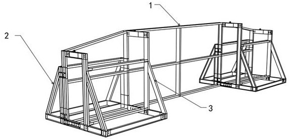
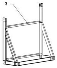
[0024] Such as Figure 1 to Figure 6 A roof truss high-efficiency turning system of the present invention is shown, including a turning chassis 1 for clamping the roof truss, a right support frame 3 for supporting the right side of the turning chassis 1, and a left support frame 3 for supporting the left side of the turning chassis 1. The support frame 2, the right support frame 3 and the left support frame 2 are all right-angle support frames; the turn-over chassis 1 is composed of a net frame 4 and one or more connecting devices; the connecting device is welded and fixed on the net frame 4 The right side is used to clamp the roof truss; one right-angled surface of the right support frame 3 is detachably connected with the connecting device (through bolts) to form a closed body and then the roof truss is clamped, and the other right-angled surface is flush with the bottom surface of the grid frame 4 (to support the right side of the turn-over chassis 1); after the turn-over o...

Embodiment 2

[0029] The difference between this embodiment and Embodiment 1 is:

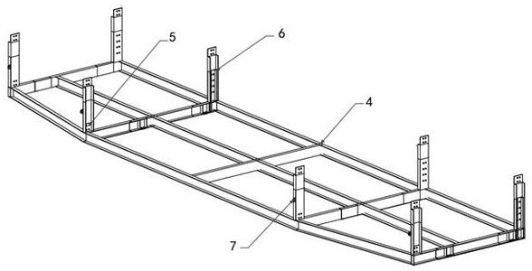
[0030] The number of the connecting device is one and is arranged on the middle part of the right side of the network frame 4, and four connecting pieces 5 are evenly arranged on the middle part of the right side of the network frame 4. In order to ensure the supporting effect, the two connecting pieces 4 at the front end The spacing between the two connecting pieces 4 at the rear end is large, and the number of the right support frame 3 connected correspondingly to it is also one. Simultaneously, the number of said left support frame 2 is one and is arranged on the middle part of the left side of the grid frame 4 .


PUM


Abstract

The invention relates to the technical field of building construction, and particularly relates to an efficient roof truss turnover system. The efficient roof truss turnover system comprises a turnover underframe used for clamping a roof truss, a right supporting frame used for supporting the right side of the turnover underframe and a left supporting frame used for supporting the left side of theturnover underframe, and the right supporting frame and the left supporting frame are right-angle supporting frames; the turnover underframe is composed of a net-shaped frame and one or more connecting devices; the connecting devices are welded and fixed to the right side face of the net-shaped frame and used for clamping the roof truss; one right-angle face of the right supporting frame is detachably connected with the connecting device to form a closed body and then clamps the roof truss, and the other right-angle face of the right supporting frame is flush with the bottom face of the net-shaped frame; after the roof truss is turned over, one right-angle face of the left supporting frame is detachably connected to the left side face of the net-shaped frame, and the other right-angle face of the left supporting frame is flush with the bottom face of the net-shaped frame. The efficient roof truss turnover system is reliable in connection, convenient to use and convenient to transfer,reduces the roof truss turnover risk during construction, saves the site, and achieves the purposes of shortening the construction period and improving the mechanical utilization rate through overallturnover.

Description

technical field [0001] The invention relates to the technical field of building construction, in particular to a high-efficiency turning system for roof trusses. Background technique [0002] In industrial buildings, a large number of prefabricated components are usually used. Among them, the production of prefabricated roof trusses needs to be prefabricated on the horizontal plane. After the strength reaches the standard, it is hoisted piece by piece. During hoisting, the risk of prefabricated roof trusses turning over is high, and it is easy to cause damage to the prefabricated roof trusses. It occupies a large area, and the roof trusses need to be placed for a period of time until the concrete strength reaches Hoisting can only be carried out after a certain strength, which is not conducive to saving the construction period. Contents of the invention [0003] In view of the above problems, the purpose of the present invention is to provide an efficient roof truss turni...

Claims


Application Information

Patent Timeline
Patent Type & Authority Applications(China)
IPC IPC(8): E04G21/16
CPCE04G21/16
Inventor 刘莲钟卫苏广洪王玉娇张黎敏
Owner THE THIRD CONSTR & ENG OF CCFED
Why Eureka
Try Eureka