
Butterfly optical cable

A butterfly-shaped optical cable and butterfly-shaped technology, applied in the direction of light guides, optics, optical components, etc., can solve the problems of inability to resist cable tension, reduce cable bearing force, and easy corrosion of hanging necks, and reduce laying costs and labor intensity, strong tensile properties, and the effect of reducing overhead density

Inactive Publication Date: 2019-10-29
武汉瑞联光通信技术有限公司
View PDF2 Cites 3 Cited by
  • Summary
  • Abstract
  • Description
  • Claims
  • Application Information

AI Technical Summary

Problems solved by technology

The construction of such a structure is relatively cumbersome. If an all-fiber network transformation is to be carried out in the future, the project must be huge, and it will take time and work to rewire the site.
[0004] Chinese patent application number: 201220363366.1 discloses a photoelectric hybrid corrugated cable, including an optical communication unit, an electrical communication unit and an outer protective sheath, the optical communication unit includes at least a pair of optical fiber cores, and the electrical communication unit includes at least one electrical communication link The corrugated cable with this structure has poor bearing and tensile capacity, and most of the cable is exposed to the outside air. After long-term sun and rain, the protective effect of the outer sheath of the cable Small
[0005] During the laying process, the most difficult place is often the photoelectric home, and the cable needs to be branched. However, the cable with better mechanical properties is more difficult to branch.
In addition, when the traditional cable is laid, a special hanging neck needs to be pulled to reduce the load bearing force of the cable. This so-called hanging neck is generally a bare steel rope, which is exposed to the air for a long time, and the hanging neck is easy to be corroded. Even disconnected, so that it cannot play the role of hanging neck instead of cable tension

Method used


Image

  • Butterfly optical cable

Examples


Embodiment Construction

[0018] The technical solutions in the embodiments of the present invention will be clearly and completely described below in conjunction with the embodiments of the present invention. Apparently, the described embodiments are only some of the embodiments of the present invention, not all of them. Based on the embodiments of the present invention, all other embodiments obtained by persons of ordinary skill in the art without making creative efforts belong to the protection scope of the present invention.

[0019] In describing the present invention, it should be understood that the terms "center", "longitudinal", "transverse", "length", "width", "thickness", "upper", "lower", "front", " Orientation indicated by rear, left, right, vertical, horizontal, top, bottom, inside, outside, clockwise, counterclockwise, etc. The positional relationship is based on the orientation or positional relationship shown in the drawings, and is only for the convenience of describing the present in...


PUM


Abstract

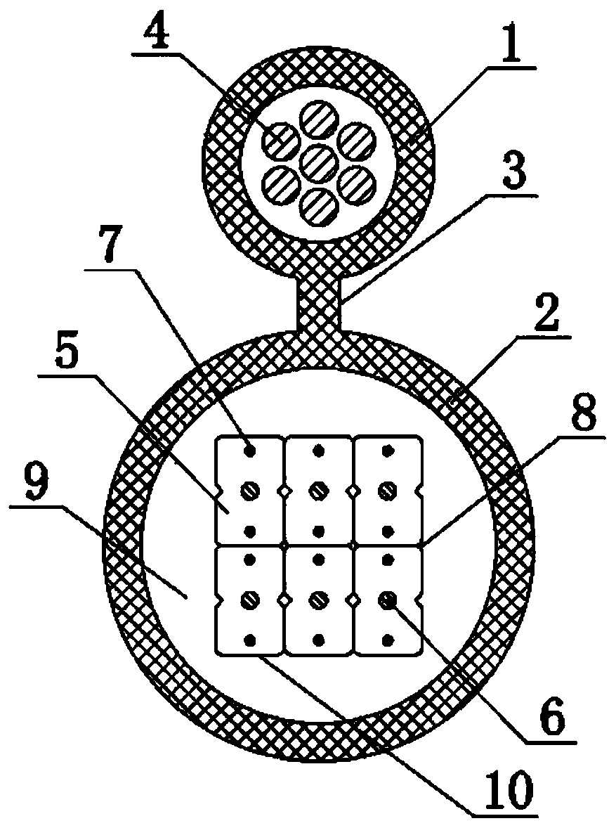
The invention relates to a butterfly optical cable which comprises a hanging neck protective sleeve, an outer protective sleeve, a hanging neck, hanging wires and butterfly optical cable subunits. Inthe butterfly optical cable, the hanging neck is arranged on each outer protective sleeve; an integrated self-supporting structure has relatively strong tensile resistance; during laying, an independent hanging neck does not need to be additionally used. Good laying performance is provided; by adopting the optical cable, overhead laying of the optical cable can be conveniently implemented; the overhead density is reduced, the optical cable laying cost and labor intensity are reduced, the optical cable laying efficiency is improved, the laying operation is simple, and time and labor are saved;parallel reinforcements are arranged in butterfly protective sleeves, the stress of the laid cable is uniform, and the mechanical properties of the butterfly optical cable are greatly improved.

Description

technical field [0001] The invention relates to the technical field of optical cables, in particular to a butterfly optical cable. Background technique [0002] With the development of optical communication, butterfly optical cables are widely used in access networks. In order to simplify construction and maintenance, a self-supporting butterfly cable that can be used both indoors and outdoors is widely used; in the outdoor section, it can be used as a self-supporting cable overhead; before the cable enters the home, the hanging neck element is cut and fixed on the On the special fixer, the remaining optical cables are removed from the hanging neck components and become butterfly optical cables to be introduced into the room, which can be used with quick-connect connectors or optical fiber cold connections. The traditional butterfly optical cable is inconvenient to lay, the construction difficulty is high, and the self-supporting strength is low. [0003] Chinese patent ap...

Claims


Application Information

Patent Timeline
IPC IPC(8): G02B6/44
CPCG02B6/443G02B6/4432G02B6/4439
Inventor 黄乔义张树兵胡占勇
Owner 武汉瑞联光通信技术有限公司
Learn More