
Absolute encoder

An absolute encoder and optical technology, applied in the field of absolute encoders, can solve the problems of lower detection accuracy of absolute rotation angle and achieve high-precision detection

Active Publication Date: 2019-10-29
MITSUBISHI ELECTRIC CORP
View PDF11 Cites 0 Cited by
  • Summary
  • Abstract
  • Description
  • Claims
  • Application Information

AI Technical Summary

Problems solved by technology

In this absolute encoder, if unnecessary light other than the light used for calculating the absolute rotation angle enters the light receiving element, the detection accuracy of the absolute rotation angle will decrease, so it is desirable to remove the unnecessary light.

Method used


Image

  • Absolute encoder
  • Absolute encoder
  • Absolute encoder

Examples


Embodiment approach 1

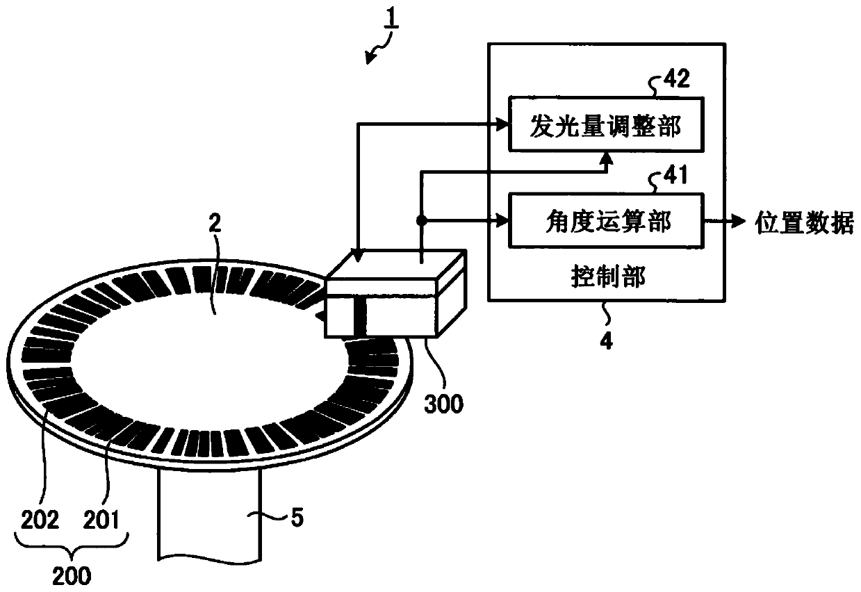
[0030] figure 1 It is a figure which shows the structure of the absolute encoder concerning Embodiment 1 of this invention. The absolute encoder 1 is a device for detecting the rotation angle of a rotating body as an object to be measured, and includes an optical scale 2 , a module package 300 , and a control unit 4 . The rotation angle detected by the absolute encoder 1 is an absolute rotation angle. In addition, in figure 1 In the drawing, the upper surface of the module package 300 , which is the surface opposite to the optical scale 2 , is shown on the lower side, and the bottom surface of the module package 300 is shown on the upper side.

[0031] The optical scale 2 is connected to a rotating shaft 5 included in a rotating device such as a motor, and rotates in accordance with the rotation of the rotating shaft 5 . The optical scale 2 is configured using a disc-shaped member. The optical scale 2 has an optical pattern 200 on the upper surface of a disc-shaped member,...

Embodiment approach 2

[0118] Next, use Figure 17 and Figure 18 Embodiment 2 of the present invention will be described. In Embodiment 2, the upper surface of the light-transmitting resin is inclined with respect to the light-receiving surface 320 of the light-receiving element 32, thereby allowing the light reflected by the light-transmitting resin to enter the light-receiving surface 320 of the light-receiving element 32. inhibition.

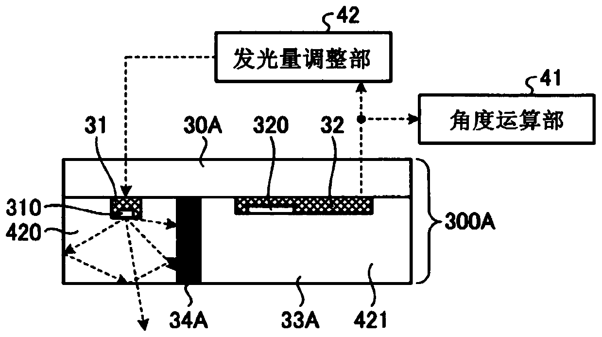
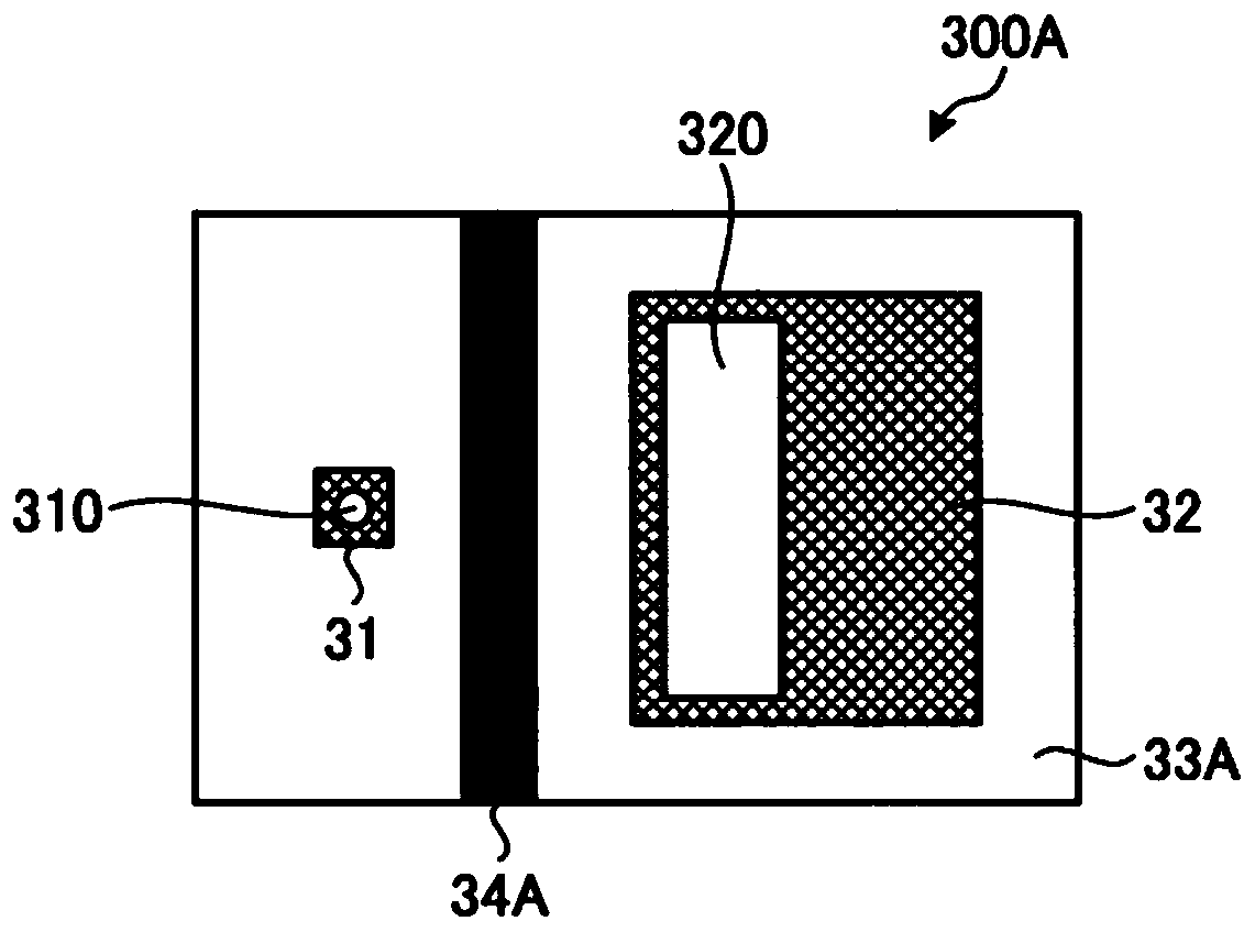
[0119] Figure 17 It is a figure which shows the 1st structural example of the module package concerning Embodiment 2. right Figure 17 The realization and figure 2 The module package 300A of Embodiment 1 shown or Figure 10 In the module package 300B according to Embodiment 1 shown, components having the same functions are denoted by the same reference numerals, and overlapping descriptions are omitted.

[0120] The module package 300C of Embodiment 2 has a package substrate 30B, a light emitting element 31 , a light receiving element 32 , a light transmi...


PUM


Abstract

An absolute encoder comprises: an optical scale having an optical pattern; a module package (300B) in which a light-emission element (31) for irradiating light onto the optical scale and a light-reception element (32) for receiving reflected light from the optical scale are covered by a light-transmitting resin (33A); and a control unit for calculating the absolute rotation angle of the optical scale on the basis of a signal output by the light-reception element (32) according to the reflected light. The module package (300B) has light-blocking resin (34B) disposed so as to be exposed at the surface of the light-transmitting resin (33A) facing the optical scale and pass through the intermediate position between the center of the light emission surface (310) of the light-emitting element (31) and the center of the light reception surface (320) of the light-reception element (32).

Description

technical field [0001] The present invention relates to an absolute encoder for detecting the absolute rotation angle of a measuring object. Background technique [0002] An absolute encoder is one of the rotary encoders for detecting the absolute rotation angle of the object to be measured. The absolute encoder is an encoder that calculates the absolute rotation angle of the optical scale based on the optical signal reflected by the optical pattern on the optical scale and incident on the light receiving element. In this absolute encoder, if unnecessary light other than the light used for calculating the absolute rotation angle enters the light receiving element, the detection accuracy of the absolute rotation angle will decrease, so it is desirable to remove the unnecessary light. [0003] In the optical encoder of Patent Document 1, a light source, a photodetector, and a light source slit are enclosed in a package, and a light shielding portion is formed at one end of th...

Claims


Application Information

Patent Timeline
IPC IPC(8): G01D5/347
CPCG01D5/347G01D5/36G01D5/34715G01D5/34776
Inventor 野口琢也久保勇治多久岛秀神保茂雄
Owner MITSUBISHI ELECTRIC CORP
Learn More