Driving assistance device, driving assistance method, and driving assistance program
一种驾驶辅助、路径生成的技术,应用在控制装置、驾驶员输入参数、运输和包装等方向,能够解决难自动行驶等问题
- Summary
- Abstract
- Description
- Claims
- Application Information
AI Technical Summary
Problems solved by technology
Method used
Image

Examples
Embodiment approach 1
[0036] ***Structure Description***
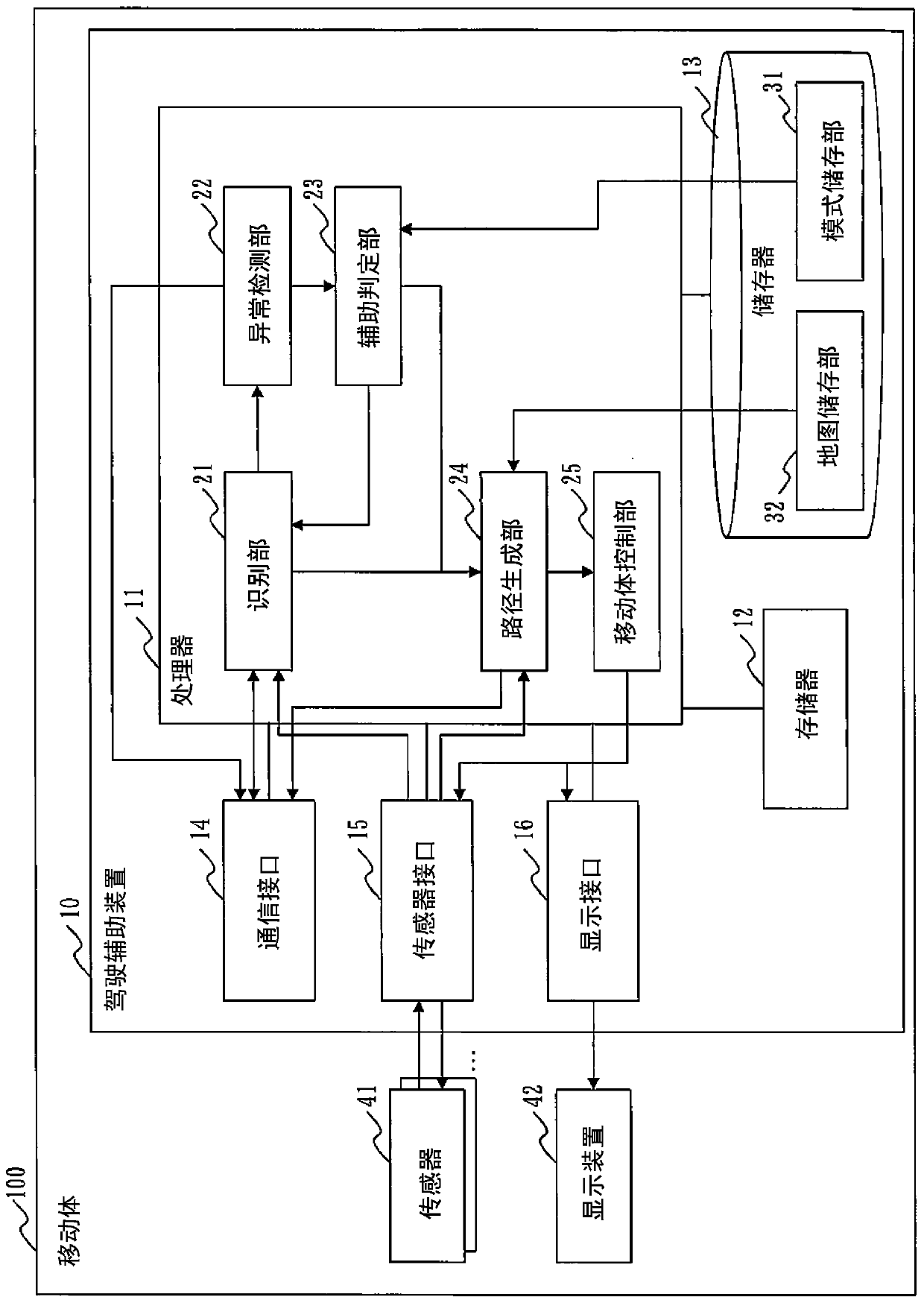
[0037] refer to figure 1 , the configuration of the driving assistance device 10 according to Embodiment 1 will be described.
[0038] figure 1 A state in which the driving assistance device 10 is mounted on the mobile body 100 is shown in . The mobile body 100 is a vehicle, a ship, or the like. In Embodiment 1, the mobile body 100 is a vehicle. In Embodiment 1, the mobile body 100 is a vehicle capable of autonomous driving. However, the mobile body 100 can perform both automatic driving and manual driving. That is, the vehicle 100 is a vehicle in which some or all of the accelerator, brakes, and steering are automatically controlled.
[0039] In addition, the driving assistance device 10 and the mobile body 100 or other components shown in the drawings may be integrated or inseparable, or may be detachable or detachable.
[0040] The driving assistance device 10 is a computer.
[0041] The driving assistance device 10 includes the ...
Deformed example 1
[0167] Figure 4 and Figure 5 An example in which a peripheral body 200 is assisted by one mobile body 100 is shown in . However, in a case where abnormality occurs in a plurality of sensors 51 and a plurality of sensing regions cannot be sensed, the mobile body 100 may coordinate with other peripheral bodies 300 to assist the peripheral body 200 .
[0168] When the mobile body 100 cooperates with other peripheral bodies 300 to assist the peripheral body 200, the moving position can be adjusted by the mobile body 100 and other peripheral bodies 300, or the moving position can be adjusted from the peripheral body 200 to the mobile body 100 and other peripheral bodies 300. Give instructions to move location. In addition, either one of the moving body 100 and the other peripheral body 300 may issue an instruction of the moving position to the other.
[0169] For example, if Figure 10 As shown in , the number of sensors required for assistance is determined for the sensing a...
Deformed example 2
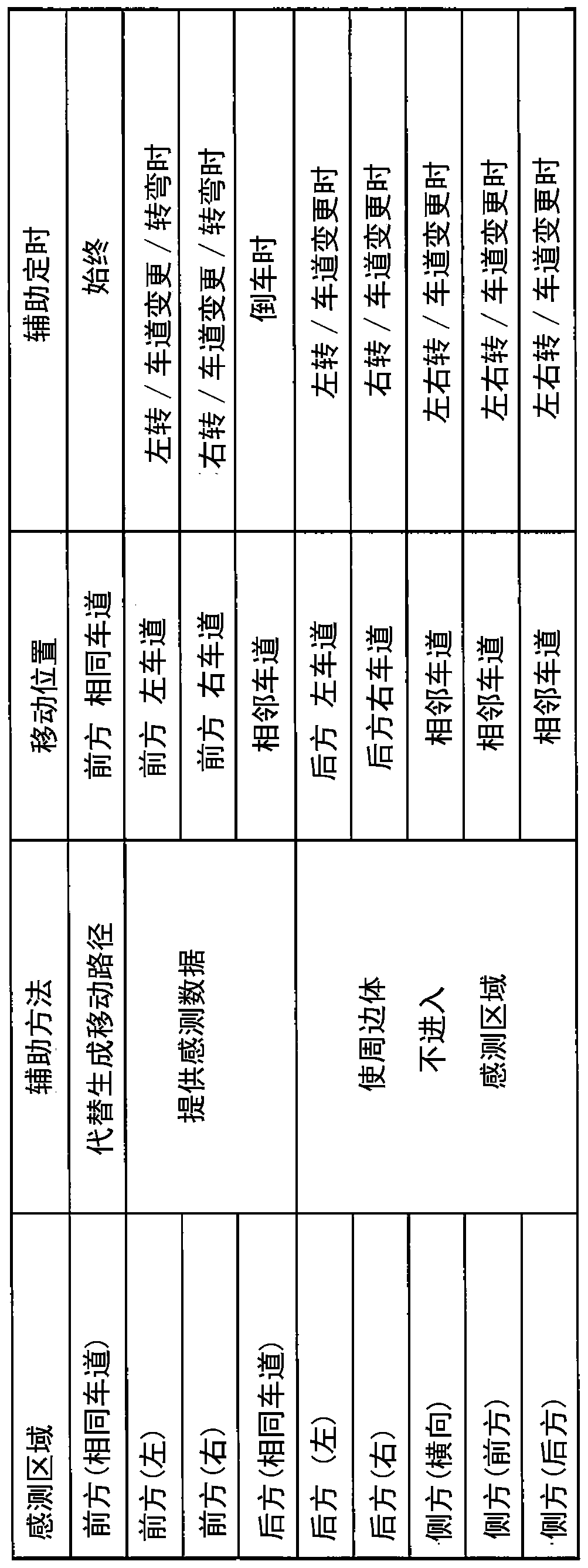
[0171] In Embodiment 1, the moving position of the mobile body 100 and the like are determined based on the sensing area of the sensor 51 in which an abnormality is detected. However, not only the sensing area of the sensor 51 but also the type of the sensor 51 may be considered to determine the moving position of the moving body 100 and the like. The type of sensor 51 refers to the classification of sensors such as millimeter wave radar, monocular camera, stereo camera, LiDAR, and sonar.
[0172] For example, if Figure 11 As shown, the control mode can be stored in the mode storage unit 31 according to the type of the sensor 51 whose abnormality is detected and the direction of the sensing area. Moreover, in Figure 6 In step S16, the auxiliary determination unit 23 may read the control mode according to the type of the sensor 51 whose abnormality is detected and the direction of the sensing area.
PUM
 Abstract
Description
Claims
Application Information
 - Generate Ideas
- Intellectual Property
- Life Sciences
- Materials
- Tech Scout
- Unparalleled Data Quality
- Higher Quality Content
- 60% Fewer Hallucinations
Browse by: Latest US Patents, China's latest patents, Technical Efficacy Thesaurus, Application Domain, Technology Topic, Popular Technical Reports.
© 2025 PatSnap. All rights reserved.Legal|Privacy policy|Modern Slavery Act Transparency Statement|Sitemap|About US| Contact US: help@patsnap.com