
Building wall reinforcing device

A technology of building walls and reinforcement devices, which is applied in construction, building maintenance, building construction, etc., can solve problems such as wall deformation, and achieve the effect of avoiding damage

Inactive Publication Date: 2019-11-01
安徽华睿水利建设有限公司
View PDF20 Cites 13 Cited by
  • Summary
  • Abstract
  • Description
  • Claims
  • Application Information

AI Technical Summary

Problems solved by technology

However, this structure cannot adapt to the slight deformation of the wall during thermal expansion and contraction and earthquakes.

Method used


Image

  • Building wall reinforcing device
  • Building wall reinforcing device
  • Building wall reinforcing device

Examples


specific Embodiment approach 1

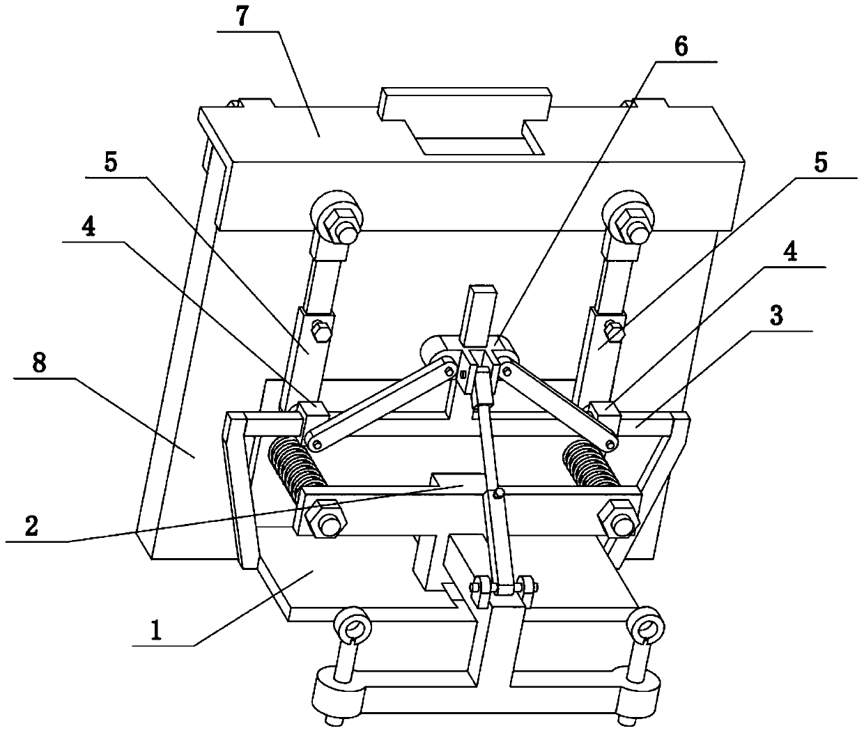
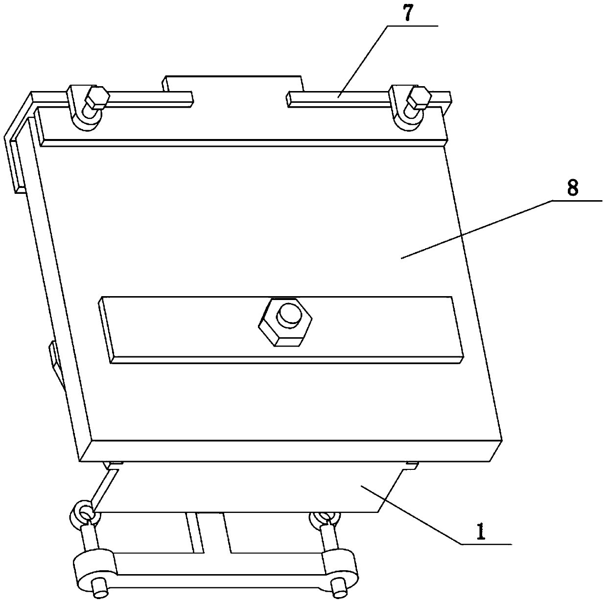
[0035] Combine below Figure 1-10 Describe this embodiment, the present invention relates to the field of construction, more specifically, a building wall reinforcement device, including a base plate 1, a wall board 102, a spring sleeve rod 103, a sliding seat 2, and left and right extension plates 201, the present invention The wall can be reinforced, and the present invention will not be completely fixed on the wall 8, and the wall 8 will be slightly deformed during thermal expansion and contraction or earthquakes, so as to avoid damage to the wall caused by being completely fixed on the wall 8.

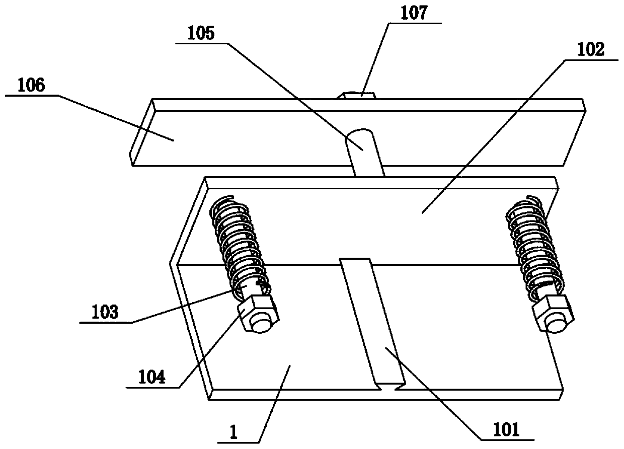
[0036] The rear side of the base plate 1 is fixedly connected with a wall board 102, and the left and right ends of the wall board 102 are fixedly connected with spring sleeves 103, and the two spring sleeves 103 are sleeved with compression springs. The lower end is slidably connected to the middle part of the base plate 1 in the front-to-back direction, and the left and right end...

specific Embodiment approach 2

[0038] Combine below Figure 1-10To illustrate this embodiment, the building wall strengthening device further includes a trapezoidal slide rail 101 , the middle part of the bottom plate 1 is provided with the trapezoidal slide rail 101 , and the lower end of the sliding seat 2 is slidably connected to the trapezoidal slide rail 101 . The sliding seat 2 realizes the adjustment of the distance between the sliding seat 2 and the wall panel 102 by sliding back and forth on the trapezoidal slide rail 101 .

specific Embodiment approach 3

[0040] Combine below Figure 1-10 To illustrate this embodiment, the building wall reinforcement device further includes a nut I104, the front ends of the two spring sleeve rods 103 are connected with the nut I104 through threads, and the two nuts I104 respectively block the front sides of the two left and right protruding plates 201 . The two nuts play a role in blocking the two left and right extending plates 201 , preventing the left and right extending plates 201 from breaking away from the corresponding spring sleeve rods 103 .


PUM


Abstract

The invention relates to the field of buildings, in particular to a building wall reinforcing device which comprises a bottom plate, a wallboard, spring sleeve rods, a sliding seat and left-right extending plates. A wall can be reinforced, the device is not thoroughly fixed to the wall, the wall is slightly deformed in the heat expansion, cold contraction and earthquake, and the device is prevented from being thoroughly fixed on the wall to damage the wall. The wallboard is fixedly connected to the rear side of the bottom plate, the spring sleeve rods are fixedly connected to the left end andthe right end of the wallboard, the two spring sleeve rods are sleeved with compression springs, the lower end of the sliding seat is in sliding connection with the middle of the bottom plate in the front-back direction, the left end and the right end of the sliding seat are fixedly connected with the left-right extending plates correspondingly, and the two left-right extending plates are in sliding connection with the two spring sleeve rods. The sliding seat is fixedly arranged, and the two compression springs are located between the wallboard and the corresponding left-right extending plates.

Description

technical field [0001] The invention relates to the construction field, in particular to a construction wall reinforcement device. Background technique [0002] The application number CN201821465910.7 discloses a wall reinforcement structure, which discloses a wall reinforcement structure, including: a wall, a composite material grid, a fixing part 1, and a mortar layer; the composite material grid passes through The fixing part one is fixed on the wall; the mortar layer is covered on the outside of the composite material grid; the composite material grid is composed of several longitudinal limbs and several transverse limbs vertically alternately and continuously arranged, and Integral molding by resin curing; the first fixing part includes: anchors and rivets; wherein two adjacent sides of the anchor are provided with grooves, and the longitudinal limbs and the transverse limbs are fixed in the grooves The rivet passes through the anchor to fix the composite grid on the w...

Claims


Application Information

Patent Timeline
Patent Type & Authority Applications(China)
IPC IPC(8): E04G23/02
CPCE04G23/0222
Inventor 田亮
Owner 安徽华睿水利建设有限公司
Learn More