A vacuum buffer tank

A technology for vacuum buffer tanks and tanks, which is applied in the field of buffer tanks, and can solve the problems that liquid-phase substances are easy to gather at the bottom of the tank and affect the vacuum degree of the buffer tank, etc.

Active Publication Date: 2020-11-13
江苏高润新材料有限公司
View PDF17 Cites 0 Cited by
  • Summary
  • Abstract
  • Description
  • Claims
  • Application Information

AI Technical Summary

Problems solved by technology

[0004] In order to make up for the deficiencies in the prior art, the present invention proposes a vacuum buffer tank. The present invention is mainly used to solve the problem that when the existing vacuum buffer tank is used to buffer the gas-phase substance containing liquid, the gas-phase substance has certain When the liquid in the vacuum buffer tank is flowing, the liquid phase substances in the gas are easy to gather at the bottom of the tank, which will affect the vacuum degree in the buffer tank for a long time; at the same time, when the liquid is discharged, it is necessary to destroy the vacuum buffer tank. of the vacuum break to discharge

Method used


Image

  • A vacuum buffer tank
  • A vacuum buffer tank
  • A vacuum buffer tank

Examples


Embodiment Construction

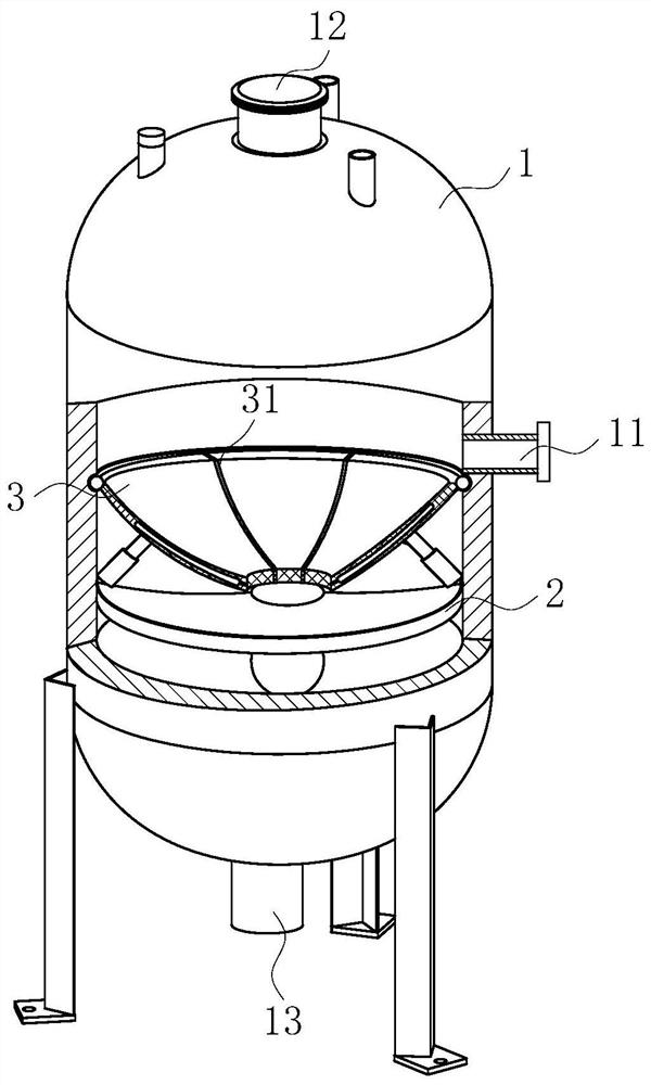
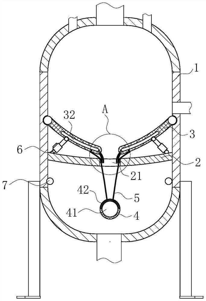
[0020] use Figure 1-Figure 4 A vacuum buffer tank according to one embodiment of the present invention will be described as follows.

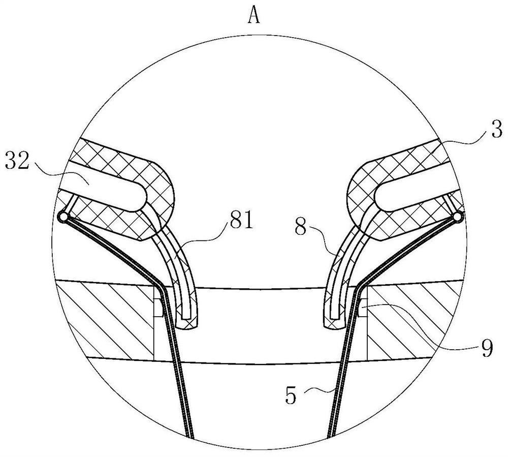
[0021] Such as Figure 1-Figure 4As shown, a vacuum buffer tank according to the present invention includes a tank body 1; an air inlet 11 is provided on the side wall of the tank body 1, and an air outlet 12 is provided at the top of the tank body 1, and the tank body The bottom end of 1 is provided with a drain port 13; the tank body 1 is equipped with a diversion recessed plate 2, and the diversion recessed plate 2 is provided with a diversion hole 21; the upper part of the diversion recessed plate 2 is installed obliquely There are a plurality of fan-shaped deflectors 3, and the plurality of fan-shaped deflectors 3 are hinged on the inner wall of the tank body 1 through hinge columns, and the fan-shaped deflectors 3 are located below the air inlet 11; each fan-shaped deflector 3 They are all connected by elastic membranes 31, and the end...


PUM


Abstract

The invention belongs to the technical field of buffer tanks, and particularly relates to a vacuum buffer tank. A flow guide concave plate is installed in a tank body, and a flow guide hole is formedin the flow guide concave plate; a plurality of fan-shaped flow guide plates are obliquely installed above the flow guide concave plate, the multiple fan-shaped flow guide plates are hinged to the inner wall of the tank body through hinge joint columns, and the fan-shaped flow guide plates are located below an air inlet; every two adjacent fan-shaped flow guide plates are connected through an elastic film, and the end of each fan-shaped flow guide plate is located above the flow guide hole; a floating ball is arranged at the bottom end of the tank body and connected with the bottom end faces of the fan-shaped flow guide plates through a plurality of elastic digging ropes; and a plurality of telescopic rods are obliquely installed on the upper surface of the flow guide concave plate, and the top ends of the telescopic rods are connected with the bottom end walls of the multiple fan-shaped flow guide plates. The situation that the vacuum degree inside the tank body is affected by excessive concentration of liquid in the tank body is effectively reduced, and meanwhile the resource waste phenomenon caused by disappearing of all vacuum inside the tank body is reduced.

Description

technical field [0001] The invention belongs to the technical field of buffer tanks, in particular to a vacuum buffer tank. Background technique [0002] Buffer water tanks are widely used in engineering, and different occasions have different names, such as intermediate storage containers, retention tanks, balance tanks, liquid receivers, mixing tanks, and containers. In fact, based on the above statement, we can make a general definition. A surge tank is one such device that enables smoother operation. Its medium can be liquid, gas phase or solid phase. The buffer tank is mainly used to buffer the pressure fluctuation of the system in various systems, so that the system works more smoothly. [0003] When the existing vacuum buffer tank is in use, when buffering the gas-phase substance containing liquid, since there is a certain amount of liquid in the gas-phase substance, when the vacuum buffer tank pairs flow, the liquid-phase substance in the gas is easy to gather int...

Claims


Application Information

Patent Timeline
Patent Type & Authority Patents(China)
IPC IPC(8): F16J12/00
CPCF16J12/00
Inventor 许良云朋仁峰
Owner 江苏高润新材料有限公司
Why Eureka
Try Eureka