
Multifunctional panel connector

A connector and multi-functional technology, applied in the direction of connection, parts of connection devices, electrical components, etc., can solve the problems of simultaneous wiring of strong wires, waste of non-renewable resources, troublesome replacement or maintenance, etc., to increase transmission The effect of distance, meeting the requirements of data transmission and appearance, and convenient maintenance and repair

Pending Publication Date: 2019-11-01
KUNSHAN SILEI ELECTRONICS TECH
View PDF6 Cites 1 Cited by
  • Summary
  • Abstract
  • Description
  • Claims
  • Application Information

AI Technical Summary

Problems solved by technology

[0002] With the improvement of people's demand for quality of life, the requirements for signal transmission in daily life are also getting higher and higher. It is required to ensure the signal transmission speed, stability and transmission distance, especially for the transmission of video and image signals. Challenges. At present, most high-quality video and image signals on the market are transmitted using HDMI cables. The existing HDMI cables are composed of 19-core copper wires. Affected by the characteristics of metal materials, the maximum transmission distance is 20 meters, and the transmission distance short
As the length increases, in order to avoid serious attenuation of the signal, it is necessary to thicken the copper wire and strengthen the signal shielding at the same time, wasting precious non-renewable resources
Traditional connecting wires cannot be wired at the same time as strong wires, and the anti-interference ability is poor, and the technology is updated quickly. In the process of user decoration and wiring, it is troublesome to install the cables in the wall if they need to be replaced or repaired. Therefore, There is an urgent need to design a high-quality transmission device that is aesthetically pleasing and can adapt to most signals

Method used


Image

  • Multifunctional panel connector
  • Multifunctional panel connector
  • Multifunctional panel connector

Examples


no. 1 example

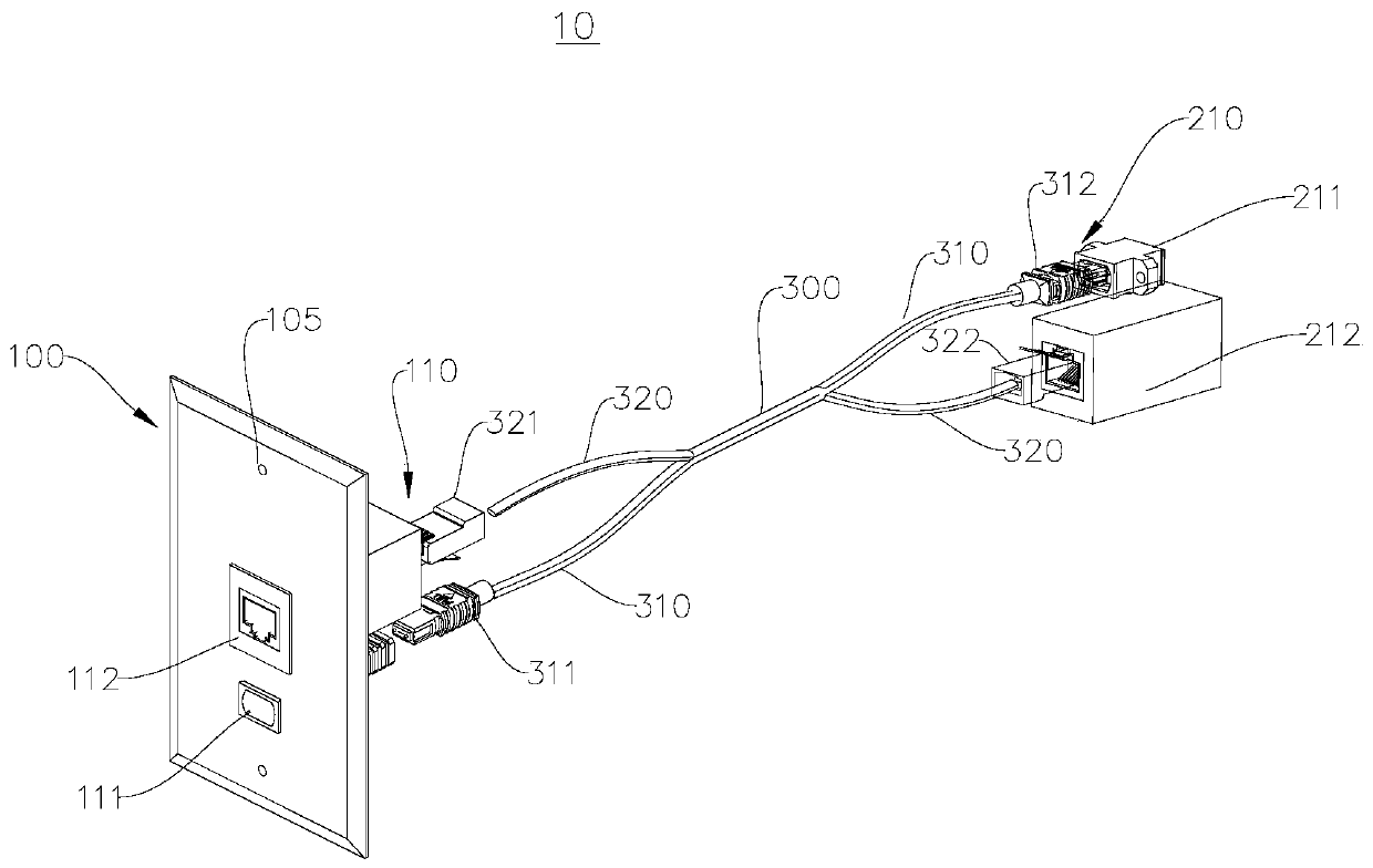
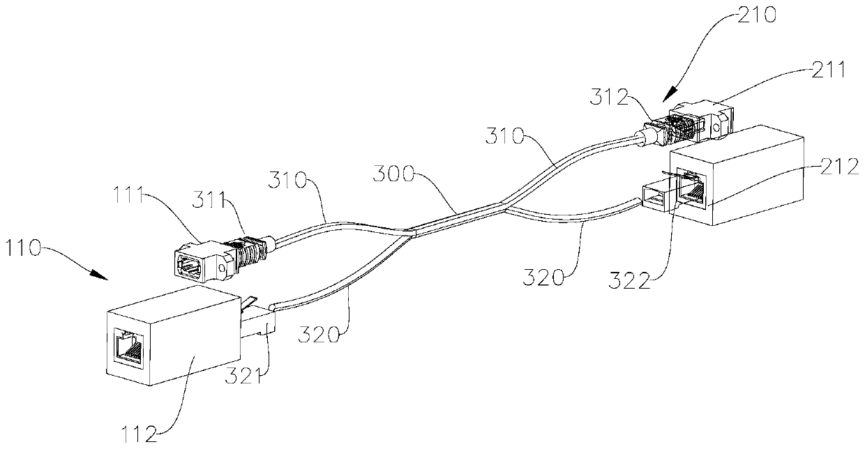
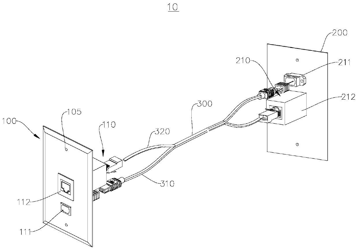
[0031] See figure 1 This embodiment provides a multifunctional panel connector 10, the multifunctional panel connector 10 includes: a first connector module 110, a second connector module 210, a transmission line 300, and at least one connection panel.

[0032] The first connector module 110 and the second connector module 210 are correspondingly arranged. For example, the first connector module 110 and the second connector module 210 are connectors arranged in pairs. One end of the transmission line 300 is connected to the first connector module 110, and the other end of the transmission line 300 is connected to the second connector module 210. The transmission line 300 is used to transmit signals between the first connector module 110 and the second connector module 210. Fast and secure transmission. For example, one of the first connector module 110 and the second connector module 210 is used to access an input signal, and the input signal is transmitted to the other connector...


PUM


Abstract

The invention provides a multifunctional panel connector. The multifunctional panel connector comprises a first connection panel, a transmission line, a first connector module and a second connector module; one end of the transmission line is connected with the first connector module, and the other end of the transmission line is connected to the second connector module, and one of the first connector module and the second connector module is used for connecting with an input signal, and the input signal is transmitted to the other one connector module through the transmission line for output.Transmission of signals through optical fiber transmission lines can avoid external influences to cause increasing the transmission distance. On the other hand, modular settings can make maintenanceand repair of the entire system more convenient and more scalable, the expandability is higher, the multifunctional panel connector can be arranged at a wall body or in a cabinet body in advance, canadapt various data ports, is high in expandability, can meet demands of users for data transmission and appearances at the same time, can perform signal transmission through optical fibers, and can meet the adapting demand of most of the signals.

Description

Technical field [0001] The present invention relates to the technical field of signal transmission devices, in particular to a multifunctional panel connector. Background technique [0002] With the improvement of people’s demand for quality of life, the requirements for signal transmission in daily life are also getting higher and higher. It is required to ensure signal transmission speed, stability and transmission distance, especially for the transmission of video and image signals. Challenges. At present, the transmission of high-quality video image signals on the market mostly uses HDMI cables for transmission. The existing HDMI cables are composed of 19-core copper wires and are affected by the characteristics of metal materials. The maximum transmission distance is 20 meters. short. As the length increases, in order to avoid serious signal attenuation, it is necessary to thicken the copper wire while strengthening signal shielding, which wastes precious non-renewable reso...

Claims


Application Information

Patent Timeline
Patent Type & Authority Applications(China)
IPC IPC(8): H01R13/502H01R13/66H01R31/02
CPCH01R31/02H01R13/502H01R13/66
Inventor 童小林曹俊星杨鑫张银鸽
Owner KUNSHAN SILEI ELECTRONICS TECH
Learn More